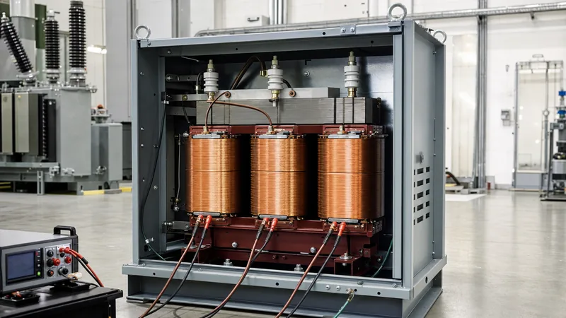
Key takeaways
- A 120v to 240v transformer operates bidirectionally, functioning as either a step-up or a step-down converter depending on winding excitation.
- Autotransformer topologies offer up to 50 percent footprint reduction and lower losses for 120V/240V conversions where galvanic isolation is not mandated.
- Continuous loads require sizing transformers at a minimum of 125 percent of the connected load per NEC Article 450 and IEEE C57.96.
- Split-phase 240V systems require careful neutral bonding to prevent floating neutral hazards and dangerous line-to-ground overvoltages.
- Factory acceptance testing under IEEE C57.12.91 verifies winding resistance, turns ratio within 0.5 percent tolerance, and dielectric withstand.
Quick answer: A 120v to 240v transformer is a single-phase magnetic device designed to step up 120V supply voltage to 240V or, when reversed, step down 240V to 120V. Sized between 0.5 kVA and 100 kVA, it serves commercial equipment, industrial controls, and imported machinery requiring voltage matching across low-voltage utility interfaces.
Voltage discrepancies between utility feeds and industrial load profiles frequently demand low-voltage transformation. While North American commercial distribution predominantly provides 120V line-to-neutral for convenience receptacles, light machinery and heating elements often require 240V single-phase supplies. Conversely, imported European equipment rated for 230V or 240V single-phase must operate from standard 120V domestic branch circuits. Specifying the correct transformer topology—whether an autotransformer or a two-winding isolation unit—dictates operational efficiency, arc-flash boundary dynamics, fault current levels, and regulatory compliance under UL 1561, IEEE C57.12.00, and NFPA 70 (National Electrical Code).
How a 120v to 240v Transformer Operates: Step-Up vs Step-Down
A 120v to 240v transformer transfers electrical energy between circuits through electromagnetic induction, governed by Faraday's law and standard turns-ratio principles defined in IEEE C57.12.00 clause 5.11.
Because magnetic flux coupling in laminated silicon steel or amorphous metal cores is inherently bidirectional, the designation of "primary" and "secondary" depends solely on power flow direction. When fed from a 120V branch circuit, the unit functions as a step-up device: the primary winding draws higher current to establish the core flux, inducing 240V across the secondary winding with half the ampacity. Conversely, when wired as a 240 to 120 volt transformer, high-voltage excitation at 240V yields 120V output at twice the rated primary current.
Understanding this magnetic symmetry is vital when configuring system protection. Reverse-feeding a standard dry-type distribution transformer—energising the intended low-voltage secondary to obtain high-voltage output—produces significantly higher inrush currents. Inrush multipliers can reach 12 to 16 times rated root-mean-square (RMS) current rather than the standard 8 to 10 times encountered in forward excitation, frequently causing nuisance tripping on upstream protective devices unless branch circuit protection is calculated to account for magnetic saturation.
Autotransformer vs Isolation Transformer for 120V and 240V Systems
Selecting between an autotransformer and a two-winding isolation transformer hinges on electrical isolation requirements, ground referencing, and physical footprint constraints.
In a standard two-winding isolation transformer, primary and secondary coils are physically and electrically separated. Dielectric barrier insulation prevents direct-current (DC) continuity and blocks common-mode electrical noise, establishing a separately derived system under NEC Article 100. This isolation enables the design engineer to establish a fresh neutral-to-ground bond on the secondary side, providing stable voltage references for sensitive industrial controls, laboratory instruments, and data-logging hardware. For further details on single-phase magnetic configurations, review our single phase transformer guide.
By contrast, an autotransformer shares a common winding across the 120V and 240V circuits, tapping the midpoint for the lower voltage. Because electrical continuity remains between input and output, an autotransformer cannot establish a separately derived system or block line surges. However, because it only transfers transformed power across the voltage differential (roughly half the total throughput power), an autotransformer designed as a 240 v transformer offers lower core and winding losses, lower percent impedance (%Z), and a footprint up to 50 percent smaller than an equivalent isolation unit.
| Engineering Metric | Two-Winding Isolation Transformer | Single-Winding Autotransformer |
|---|---|---|
| Galvanic Isolation | Yes (Dielectric withstand > 2.5 kV) | No (Direct copper conduction) |
| Full-Load Efficiency (%) | 96.5 – 98.2 | 98.5 – 99.4 |
| Impedance (%Z at 60 Hz) | 3.0 – 5.5% | 1.0 – 2.5% |
| Footprint & Weight Ratio | 1.0 (Baseline) | 0.50 – 0.65 |
| Cost Index (approximate) | 1.0 (Baseline) | 0.60 – 0.75 |
| Separately Derived System | Yes (NEC Article 250.30 compliant) | No (Shares source neutral/ground) |
Sizing Calculations and Inrush Current Considerations
Accurately sizing a 120v to 240v transformer requires calculating the steady-state apparent power demand while incorporating continuous load margins and magnetic inrush characteristics.
Under NEC Article 450.3 and IEEE C57.96, continuous loads (operating for three hours or more) must not exceed 80 percent of the transformer's nominal kVA rating. This establishes a mandatory 125 percent sizing multiplier for commercial and industrial installations. Engineers can calculate full-load current ($I$) and required apparent power ($S$) using the following equations:
$$S = V \times I$$
$$S_{\text{design}} = S_{\text{load}} \times 1.25$$
Consider an industrial conditioning chamber rated at 240V, drawing 18.5 A single-phase resistive-inductive load:
- Calculate the nominal load power: $S_{\text{load}} = 240\text{ V} \times 18.5\text{ A} = 4,440\text{ VA} = 4.44\text{ kVA}$.
- Apply the continuous-use multiplier: $S_{\text{design}} = 4.44\text{ kVA} \times 1.25 = 5.55\text{ kVA}$.
- Select standard commercial kVA rating: Specify a 7.5 kVA unit, as the next standard rating above 5 kVA.
- Calculate primary current on the 120V side at 7.5 kVA capacity: $I_1 = 7,500\text{ VA} / 120\text{ V} = 62.5\text{ A}$.
- Calculate secondary current on the 240V side: $I_2 = 7,500\text{ VA} / 240\text{ V} = 31.25\text{ A}$.
Designers must coordinate overcurrent protective devices (OCPD) to accommodate instantaneous magnetic inrush. Transformers below 9 kVA often demonstrate inrush peaks equal to 12 to 15 times nominal current for the first 3 to 10 cycles (50 to 160 milliseconds). Using standard thermal-magnetic circuit breakers can lead to nuisance trips; consequently, breakers compliant with IEC 60947-2 Curve D or inverse-time circuit breakers sized per NEC Table 450.3(B) are recommended for reliable branch protection in an industrial power system installation.
Wiring and Terminal Configurations: Split-Phase vs Single-Phase
Wiring a 120v to 240v transformer depends on whether the load requires a 240V two-wire output or a 120/240V three-wire split-phase system with an earthed neutral centre tap.
Modern dry-type units are typically engineered with dual primary and dual secondary windings (often labelled H1, H2, H3, H4 and X1, X2, X3, X4). Connecting windings in series doubles the operational voltage rating, while parallel connections double the current-carrying capacity while maintaining voltage. Terminal cross-connections must strictly follow polarity markings (subtractive polarity being standard under IEEE C57.12.00 for distribution units):
- 120V to 240V Step-Up (Two-Wire): Connect input 120V across parallel primary terminals (H1 tied to H3; H2 tied to H4). Connect secondary coils in series (jumper X2 to X3), taking the 240V output across terminals X1 and X4.
- 240V to 120/240V Split-Phase (Three-Wire): Connect 240V across series primary terminals (jumper H2 to H3; supply to H1 and H4). Connect secondary windings in series (jumper X2 to X3). The 240V line-to-line output is taken across X1 and X4, while the center-tap junction serves as the grounded neutral conductor, providing 120V from X1-to-neutral and 120V from X4-to-neutral.
Improper series-parallel jumper arrangements will result in opposing magnetomotive forces, short-circuit loops, or severe core saturation, leading to immediate trip of protective devices or permanent winding burnout.
Protection, Grounding and NEC Article 450 Compliance
Protective coordination and system grounding for any 120v to 240v transformer installation must adhere strictly to NEC Article 450 and Article 250 to mitigate shock hazards and equipment damage.
Under NEC Table 450.3(B), when secondary overcurrent protection is not provided, the primary OCPD must not exceed 125 percent of the rated primary current for transformers rated 9 A or greater. If 125 percent does not correspond to a standard fuse or breaker rating, NEC 450.3(B) Exception No. 1 permits rounding up to the next standard rating. Alternatively, where primary and secondary protection are both deployed, the primary protective device may be sized up to 250 percent, provided secondary protection does not exceed 125 percent of nominal secondary ampacity.
System earthing dictates operational safety. When installing an isolation-type 240 to 120 volt transformer feeding 120V branch circuits, the secondary neutral (center tap) must be connected to the grounding electrode conductor (GEC) via an appropriately sized main bonding jumper per NEC 250.28. Enclosure grounding must maintain low impedance to clear ground faults rapidly, ensuring integration complies with low-voltage assemblies specified under IEC 61439 low-voltage switchgear engineering principles.
Factory Testing and Commissioning Checklist
Factory and field testing ensures that each 120v to 240v transformer complies with insulation, loss, and impedance specifications before site energisation.
Prior to dispatch, quality manufacturers execute routine factory tests under IEEE C57.12.91 and IEC 60076-11. Technicians and site engineers can verify performance by performing the commissioning steps outlined below:
- Insulation Resistance Testing: Apply a 1,000V DC megohmmeter between primary windings and ground, secondary windings and ground, and between primary and secondary windings for 60 seconds; minimum resistance must exceed 100 megohms at 20 degrees Celsius.
- Voltage Turns Ratio (VTR) Verification: Measure the ratio across all taps using a precision turns-ratio tester. Ratio error must remain within plus or minus 0.5 percent of nominal nameplate ratings per IEEE C57.12.00 clause 9.1.
- Winding Resistance Measurement: Measure direct-current coil resistance with a micro-ohmmeter; phase-to-phase deviations must not exceed 2.0 percent after temperature correction. Learn field procedures in our guide on how to test a transformer.
- Polarity and Phase Relationship Check: Verify subtractive polarity markings to confirm proper instantaneous voltage additive characteristics across terminals.
- No-Load Core Loss and Exciting Current: Measure excitation current at rated terminal voltage; high no-load current indicates core delamination or interlaminar insulation failure.
Next steps: specifying and sourcing
When specifying a 120v to 240v transformer for custom machinery, control panels, or infrastructure upgrades, compile complete site parameters including required kVA rating, ambient operating temperature, enclosure NEMA/IP ingress rating, duty cycle, and acoustic noise limits. Review our range of heavy-duty dry-type transformers and pad-mounted solutions for industrial facilities, or examine our pole-mounted transformers for utility distribution projects. For custom voltage tappings, electrostatic shielding, or rapid lead-time manufacturing, submit your electrical single-line diagrams directly to our engineering team through our transformer quotation portal.
Frequently asked questions
Can a 120v to 240v transformer be used in reverse?
Yes, standard two-winding distribution transformers and autotransformers are inherently bidirectional. A unit designed for 120V to 240V step-up duty can be back-fed with 240V to step down to 120V, though primary protection must be adjusted for higher inrush currents.
What is the difference between an autotransformer and an isolation transformer?
An autotransformer utilizes a single continuous copper winding with intermediate taps, sharing electrical connections between primary and secondary circuits. An isolation transformer features completely separate physical windings, providing galvanic isolation, common-mode noise suppression, and independent neutral earthing capability.
How do I calculate the correct breaker size for a 120v to 240v transformer?
Calculate nominal full-load primary current by dividing rated volt-amperes by supply voltage, then apply NEC Table 450.3(B). For transformers with primary-only protection rated over 9 A, size the breaker at 125 percent of primary current, selecting the next standard breaker size up if needed.
Can a 120v to 240v transformer run 50 Hz equipment on a 60 Hz supply?
No, a standard transformer changes voltage only, not electrical frequency. Operating a 50 Hz rated motor or load on 60 Hz changes operational speed and reactance; frequency conversion requires a variable frequency drive (VFD) or power electronic conversion system.
Why is my 240 v transformer buzzing loudly after installation?
Excessive transformer hum is typically caused by core magnetostriction amplified by loose mounting bolts, resonant metal enclosures, harmonic distortion from non-linear loads, or overvoltage excitation exceeding the core's magnetic flux density rating.
Tags: 120v to 240v transformer 240 to 120 volt transformer 240 v transformer step-down transformers single phase transformer


