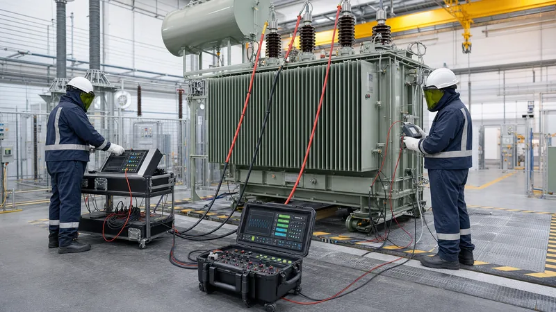
Key takeaways
- Transformer winding resistance testing requires four-wire Kelvin bridge measurement corrected to a reference temperature of 75°C or 85°C according to IEC 60076-1.
- Turns ratio measurements must match the calculated nameplate ratio within a strict tolerance of ±0.5% across every tap position per IEEE C57.12.00 standards.
- Insulation resistance evaluation relies on the Polarisation Index (10-minute to 1-minute ratio), where values exceeding 2.0 indicate healthy, moisture-free solid insulation.
- High voltage applied overvoltage tests apply AC potential at 50 Hz or 60 Hz for 60 seconds to verify the dielectric clearance between windings and earth.
- Dissipation factor or Tan Delta testing assesses bulk dielectric losses in the insulation system, with healthy liquid-immersed units exhibiting values below 0.5% at 20°C.
Quick answer: To test a transformer, isolate and ground all terminals, conduct visual inspections, and execute a sequence of diagnostic measurements comprising insulation resistance, winding resistance, voltage turns ratio, magnetic balance, and dissipation factor (tan delta), followed by high-voltage dielectric withstand tests in accordance with IEC 60076 or IEEE C57.12.
Understanding how to test a transformer correctly is essential for commissioning engineers, plant operators, and high-voltage maintenance technicians. Power and distribution assets undergo severe thermal, mechanical, and electrical stresses throughout their operating life. Establishing rigorous baseline diagnostics and routine assessment regimes prevents catastrophic dielectric breakdown, unscheduled outages, and costly equipment replacement. Whether you are dealing with cast resin units or mineral oil-filled units detailed in our oil-immersed vs dry-type transformers comparison, standardised electrical diagnostics confirm whether internal clearances, magnetic circuits, and conductive assemblies remain within operational tolerances.
A comprehensive testing protocol validates that modern transformers meet international safety benchmarks prior to energisation. Standard frameworks such as IEC 60076-1, IEC 60076-3, IEEE C57.12.00, and IEEE C57.12.90 govern both factory acceptance routines and on-site commissioning procedures. Applying these test methods verifies that the internal electromagnetic assembly, described in our guide on transformers internal components, has survived transit, storage, and installation without mechanical displacement or insulation degradation.
Essential Safety Rules and Preparation for Electrical Transformer Testing
Electrical transformer testing requires strict adherence to isolation, residual charge dissipation, and safe clearance boundaries before connecting any diagnostic instrumentation. High-voltage transformers possess substantial capacitive properties capable of retaining lethal electrical charges long after disconnection from the primary network.
Before executing any test routine, personnel must isolate the asset from all medium-voltage and low-voltage switchboards, lock off incoming breakers, and apply temporary personal protective earthing leads to all primary, secondary, and tertiary bushings. The following safety and preparatory measures are mandatory under IEC 61936-1 and NFPA 70E:
- Positive Isolation and Verification: Visually confirm air breaks on disconnect switches and verify zero potential across all phase terminals using calibrated voltage detectors rated for the system voltage.
- Earthing and Discharge: Fit mechanical earthing clusters to all high-voltage (HV) and low-voltage (LV) terminals. Solidly bond the main transformer tank earth to the primary substation ground grid with copper conductors sized for fault current capacity.
- Neutral and Surge Arrester Disconnection: Disconnect system neutral grounding resistors, neutral earthing links, and surge arresters to isolate the transformer windings from external circuit paths during DC and high-voltage measurements.
- Atmospheric and Temperature Logging: Measure and record ambient temperature, relative humidity, and top-oil/winding temperature. Insulation resistance and winding resistance values vary drastically with temperature and must be normalised to 20°C or 75°C for meaningful analysis.
- Safety Perimeter: Erect safety barriers with warning signs at a minimum clearance distance matching the basic impulse insulation level (BIL) requirements of the highest voltage terminal under test.
How to Test Transformer Windings: Resistance and Continuity
You test transformer windings for DC resistance using a digital low-resistance ohmmeter operating on the four-wire Kelvin principle to detect loose joints, open strands, or tap-changer contact wear. This measurement detects broken parallel conductor strands, defective crimps, loose internal busbar bolting, and excessive contact resistance within de-energised tap changers (DETC) or on-load tap changers (OLTC).
Because transformer windings exhibit immense inductance (often exceeding tens of Henrys on large HV windings), applying a direct current causes a prolonged inductive transient before the current stabilizes: I(t) = (V/R) × [1 - exp(-t × R / L)]. Test instruments must deliver adequate compliance voltage (typically 30 V to 50 V DC) to saturate the magnetic core rapidly and achieve steady-state current.
- Connect the current leads of the micro-ohmmeter to the phase terminals (e.g., 1U to 1V) and attach the potential sense leads inside the current injection points to eliminate test lead resistance.
- Inject direct current, typically selecting a current magnitude between 1% and 10% of the winding rated continuous current, ensuring test current does not exceed 10% to prevent local conductor heating.
- Wait for core saturation until the digital resistance reading stabilizes within ±0.1% over a 15-second interval.
- Record the measured resistance value in milliohms or micro-ohms alongside the actual winding temperature.
- Cycle through every tap position for tap-changing windings, recording each individual tap resistance to evaluate contact transition uniformity.
- Discharge the winding inductance safely through the test set discharge circuit before disconnecting leads.
Per IEC 60076-1 clause 10.2, phase-to-phase resistance measurements on identical winding branches must deviate by no more than 2.0% to 3.0% from each other. When converting values to the design reference temperature (typically 75°C for Class A insulation or 85°C for higher classes), apply the standard copper temperature correction equation: R_ref = R_meas × (234.5 + T_ref) / (234.5 + T_meas), where 234.5 represents the inferred zero resistance temperature for electrolytic copper (use 225 for electrical-grade aluminium).
Measuring Voltage Ratio and Vector Group Verification
A turns ratio test verifies that the physical ratio of primary to secondary turns corresponds precisely to the design transformation ratio specified on the rating plate. Turns ratio errors expose short-circuited turns, winding deformation, or incorrect tap connections inside the tank.
The test is performed using an automated transformer turns ratio (TTR) meter that injects an excitation voltage (typically 8 V to 250 V AC single-phase or three-phase at 50 Hz/60 Hz) into the higher-voltage winding while measuring the induced voltage on the corresponding lower-voltage winding. In accordance with IEEE C57.12.00 and IEC 60076-1, the measured voltage ratio must not deviate by more than ±0.5% from the nominal design ratio calculated from the rated terminal voltages at all tap positions.
Simultaneously, vector group verification confirms the internal angular phase displacement between the primary and secondary line voltages, such as the common 30-degree phase shift seen in Dyn11 configurations. As detailed in our comprehensive guide on transformer vector groups explained, verifying the phase displacement is essential before operating units in parallel. An incorrect connection angle causes severe circulatory cross-currents that will trip feeder protection immediately upon energisation.
Insulation Resistance and Polarisation Index Testing
Insulation resistance testing applies direct-current test voltages between isolated windings and the grounded tank to assess bulk dielectric integrity and contamination. This procedure establishes whether solid insulation materials, such as pressboard, Nomex, or epoxy resin, have absorbed atmospheric moisture, accumulated conductive dust, or suffered thermal degradation.
Testing requires an automated megaohmmeter applying 1,000 V to 5,000 V DC for high-voltage assets. Technicians record the insulation resistance value after 15 seconds, 60 seconds, and 10 minutes (600 seconds) of sustained DC potential. Two mathematical ratios are extracted from this dataset:
- Dielectric Absorption Ratio (DAR): The ratio of the resistance recorded at 60 seconds to that at 30 seconds: DAR = R_60s / R_30s. A value above 1.3 indicates sound, dry insulation.
- Polarisation Index (PI): The ratio of the resistance recorded at 10 minutes to that at 1 minute: PI = R_10min / R_1min.
Under IEEE 43 and IEEE C57.152 recommendations, a Polarisation Index value below 1.5 indicates excessive moisture content, contamination, or serious thermal ageing within the solid cellulose structure, demanding thermal dry-out or oil reclamation. A PI value exceeding 2.0 reflects clean, dry insulation. Test configurations must evaluate every boundary: HV winding to LV winding (with tank grounded), HV winding to Earth (with LV grounded to tank), and LV winding to Earth (with HV grounded to tank).
Dielectric Dissipation Factor and Power Factor (Tan Delta) Testing
Dissipation factor testing, commonly known as Tan Delta or power factor testing, measures the ratio of resistive leakage current to capacitive charging current flowing through an insulation system under alternating electrical stress. This AC test serves as one of the most sensitive indicators of uniform insulation deterioration, oil contamination, and water ingress.
When an AC sinusoidal voltage is applied to an ideal dielectric, the resulting current leads the voltage by exactly 90 degrees. In practical transformer insulation, microscopic dielectric losses and ionic conductivity cause a minor in-phase loss current I_R, tilting the total current by a small loss angle δ. The tangent of this angle is the dissipation factor: tan δ = I_R / I_C.
Test sets operate at line frequency or variable frequencies (typically 15 Hz to 400 Hz) using an internal test potential between 2 kV and 10 kV AC, provided this voltage remains safely below the operational rating of the winding. Measurements are executed under three primary modes using the Schering bridge or capacitive divider principle:
- Grounded Specimen Test (GST): Measures total leakage current flowing from the energised terminal to all grounded surfaces, encompassing both the tank and the ground plane.
- Grounded Specimen Test with Guard (GST-Guard): Directs selected parasitic current paths away from the measurement circuit, isolating specific internal insulation sections.
- Ungrounded Specimen Test (UST): Measures current flow exclusively between two ungrounded terminals, such as HV winding to LV winding, bypassing the tank entirely.
For modern mineral oil-immersed transformers, the measured power factor corrected to 20°C should remain below 0.5% (0.005) for new factory equipment per IEEE C57.152, and must not exceed 1.0% in service. Values approaching or exceeding 2.0% indicate critical moisture absorption, sludge formation, or severe carbonisation, requiring immediate oil degasification, filtration, or complete overhaul.
High Voltage Testing of Transformer: Applied and Induced Overvoltage
High voltage testing of transformer units verifies that the dielectric clearances and insulating barriers withstand operational overvoltages, transient switching surges, and lightning phenomena without insulation puncture or flashover. These tests form the cornerstone of factory proof testing and post-repair requalification under IEC 60076-3.
Dielectric withstand verification relies on two complementary high-potential testing methodologies:
- Separate Source AC Withstand Test (Applied Voltage Test): A high-voltage test transformer applies a single-phase AC potential at 50 Hz or 60 Hz between the tested winding (with all its phase terminals tied together) and the transformer tank, with all other windings solidly grounded. The full test voltage—such as 28 kV RMS for a 12 kV rated winding, or 50 kV RMS for a 24 kV winding per IEC 60076-3—is maintained continuously for 60 seconds. Any sudden voltage drop or surge in supply current indicates irreversible dielectric breakdown.
- Induced AC Overvoltage Withstand Test: Because applying double the rated voltage to a grounded winding from an external source would saturate the magnetic core, the induced test energises one winding (typically the LV winding) at an elevated frequency, such as 100 Hz, 150 Hz, or 200 Hz. The elevated frequency prevents core saturation while allowing the induced phase-to-phase and turn-to-turn voltage to reach twice the nominal working potential (200% rated voltage). This tests the inter-turn, inter-layer, and inter-phase insulation integrity for a test duration determined by: t = 120 × (nominal frequency / test frequency) seconds, with a minimum duration of 15 seconds.
During induced voltage testing on high-voltage and extra-high-voltage units, partial discharge (PD) monitoring is conducted simultaneously. In accordance with IEC 60270, PD levels must remain below specified limits (typically < 100 pC to 300 pC at 1.3 to 1.5 times the maximum system voltage) to guarantee that no destructive electrical tracking occurs within internal voids or oil ducts.
Magnetic Balance, Excitation Current, and Core Ground Testing
Magnetic balance and excitation current measurements detect mechanical displacement of the core limbs, flux leakage, shorted core laminations, or residual magnetization resulting from fault interruptions. These tests assess the health of the laminated silicon steel magnetic circuit without requiring tank de-tanking or internal visual entry.
The magnetic balance test applies a single-phase AC voltage (typically 230 V AC) across one phase of a star-connected HV winding (e.g., terminal 1U to 1N) while recording the induced voltages across the remaining two phases (1V-1N and 1W-1N). In a standard three-limb core-form transformer:
- Exciting the outer limb U induces roughly 60% to 90% of the applied voltage on the central limb V, and 10% to 40% on the opposite outer limb W, such that V_U = V_V + V_W.
- Exciting the central limb V distributes magnetic flux symmetrically, inducing approximately 50% of the test voltage equally across outer limbs U and W (V_U ≈ V_W ≈ 0.5 × V_V).
- Exciting the remaining outer limb W replicates the inverse of the first test: V_W = V_V + V_U.
Any significant divergence from these proportions signals physical core shifting, inter-laminar insulation failure, or shorted turns. Simultaneously, an excitation current test measures the milliampere current draw during low-voltage AC energisation. Outer limbs typically draw similar currents, whereas the central limb draws slightly lower current due to its lower magnetic reluctance path. A damaged core or shorted winding turn causes the excitation current on the affected phase to rise significantly above expected levels.
Finally, core ground continuity testing isolates the intentional core grounding strap (often brought out through a dedicated bushing on the cover). A 1,000 V DC insulation test applied between the isolated core and the main grounded tank must read greater than 100 MΩ. A low resistance reading or dead short indicates unintentional, secondary core grounding points, which generate closed loops that circulate massive eddy currents, causing localized hot spots and thermal gassing.
Complete Power Transformer Testing Matrix: Field vs Factory Acceptance
A standardized power transformer testing matrix separates routine, type, and field commissioning tests to verify compliance with technical specifications and warranty requirements. Engineering teams should consult our detailed transformer factory acceptance testing checklist when reviewing manufacturer documentation.
The following table delineates test categories, international standard references, and actionable acceptance criteria across field and factory environments:
| Diagnostic Test Description | Governing Standard | Factory Acceptance (FAT) | Field Commissioning (SAT) | Standard Acceptance Criteria |
|---|---|---|---|---|
| Winding DC Resistance | IEC 60076-1 / IEEE C57.12.90 | Routine | Mandatory | Phase deviation ≤ 2.0%; matches factory baseline within ±1% (corrected to 75°C) |
| Voltage Ratio & Vector Group | IEC 60076-1 / IEEE C57.12.00 | Routine | Mandatory | Ratio error ≤ ±0.5% of nameplate; correct angular phase relationship |
| Insulation Resistance & PI | IEEE C57.152 / IEEE 43 | Routine | Mandatory | PI > 2.0 (min 1.5); R_60s > 1,000 MΩ at reference 20°C |
| Dissipation Factor (Tan δ) | IEEE C57.152 / IEC 60076-1 | Routine | Recommended | Tan δ ≤ 0.5% for new oil-filled units (≤ 1.0% in service) at 20°C |
| Applied Overvoltage (AC Hi-Pot) | IEC 60076-3 / IEEE C57.12.00 | Routine | Optional / Reduced (80%) | Withstand rated AC test potential for 60 seconds without dielectric breakdown |
| Induced Voltage Withstand | IEC 60076-3 / IEEE C57.12.90 | Routine | Special Requirement | Withstand 200% rated voltage at elevated frequency (100–200 Hz) without flashover |
| Magnetic Balance & Excitation | IEEE C57.152 | Optional | Mandatory | Symmetrical flux distribution; outer limbs within ±5% of each other |
| Core-to-Ground Insulation | IEEE C57.152 | Routine | Mandatory | Insulation resistance > 100 MΩ at 1,000 V DC |
| Insulating Fluid Dielectric Breakdown | IEC 60156 / ASTM D877 / D1816 | Routine | Mandatory (Liquid Units) | Breakdown voltage ≥ 60 kV (new oil, 2.5 mm gap per IEC 60156) |
| Dissolved Gas Analysis (DGA) | IEC 60599 / IEEE C57.104 | Routine | Mandatory Baseline | Gas concentrations below Condition 1 limits (e.g., Acetylene C2H2 < 1 ppm) |
Step-by-Step Transformer Testing Procedure for Commissioning
Executing an electrical transformer testing procedure in the correct sequence prevents false diagnostic readings and protects sensitive test instrumentation from damage. Completing DC tests prior to AC dissipation or turns ratio testing can impart residual core magnetization, which distorts subsequent excitation measurements unless proper demagnetisation is conducted.
Follow this chronological step-by-step commissioning sequence on site:
- Perform Initial Inspection and Checks: Verify tank earthing, mechanical integrity, bushing oil levels, silica gel desiccant color, pressure relief device pin setting, gas relay float freedom, and terminal torque settings against project specifications.
- Sample and Test Insulating Liquid: For liquid-immersed transformers, extract top and bottom fluid samples in airtight syringes. Verify dielectric breakdown voltage (BDV ≥ 60 kV), moisture content (≤ 10 ppm per IEC 60814), acidity, and baseline dissolved gas concentrations.
- Execute Core and Frame Ground Insulation Checks: Disconnect the external core ground link and apply 1,000 V DC to verify that the core and core-clamping frame are each isolated from the tank with resistance exceeding 100 MΩ. Re-install the link securely after testing.
- Conduct Insulation Resistance and Polarisation Index Tests: Apply 2.5 kV or 5 kV DC to record 15-second, 60-second, and 10-minute resistance values across HV-LV, HV-Ground, and LV-Ground. Compute the DAR and PI figures.
- Perform Transformer Turns Ratio (TTR) and Phase Displacement: Connect the three-phase turns ratio meter and step through all tap settings from Tap 1 to Tap N. Validate ratio compliance within ±0.5% and confirm vector rotation matches the nameplate drawing.
- Perform Magnetic Balance and Excitation Current Tests: Inject 230 V AC single-phase on the HV windings, recording the voltage distribution and milliampere draw across each limb to verify magnetic symmetry.
- Measure Winding Resistance Across All Taps: Use a four-wire Kelvin digital micro-ohmmeter to measure DC resistance on all HV and LV phases across every tap position. Apply core demagnetisation routines via the test set upon test completion.
- Conduct Tan Delta and Capacitance Measurements: Apply variable-frequency AC potential up to 10 kV to determine winding and bushing capacitance and dissipation factors, normalising results to 20°C.
- Apply Final De-earthing and Pre-Energisation Restoration: Reconnect all control wiring, neutral earthing links, CT shorting blocks, and temperature probe cables. Confirm that all test jumpers and temporary safety cluster grounds have been removed.
Next steps: specifying and sourcing
To obtain reliable quotation proposals for custom-engineered equipment, engineering teams must supply precise technical parameters. When submitting specifications, include nominal rated power (kVA or MVA), primary and secondary rated voltages, BIL insulation ratings, vector configuration, short-circuit impedance percentage (%Z), tap-changer type (DETC or OLTC), and ambient operating conditions.
Review our factory manufacturing programs for medium-voltage infrastructure across our dedicated product portfolios, including high-efficiency power transformers, indoor cast-resin dry-type transformers, and robust outdoor oil-immersed transformers. For complete equipment packages or custom FAT inspection protocols, contact our senior application engineers directly through our transformer quotation request page or send your tender schedules via our engineering contact portal.
Frequently asked questions
how to test a transformer
To test a transformer, isolate and ground all terminals, visually inspect the unit, and perform diagnostic checks including insulation resistance, turns ratio, winding resistance, and oil dielectric strength. Compare results against IEC 60076 or IEEE C57 standards to verify electrical integrity.
What is the acceptable turns ratio tolerance for power transformers?
The measured voltage turns ratio must not deviate by more than ±0.5% from the calculated nameplate ratio across all tap positions. This strict limit is mandated by both IEEE C57.12.00 and IEC 60076-1 standards to prevent circulatory currents and output voltage deviations.
Why must transformer winding resistance be corrected for temperature?
Winding resistance must be corrected for temperature because the electrical resistance of copper and aluminium conductors changes significantly with thermal variation. Normalising measurements to 75°C or 85°C enables direct comparison against factory baseline test certificates and between phases.
What Polarisation Index value indicates healthy transformer insulation?
A Polarisation Index (PI) value of 2.0 or greater indicates clean, dry, and healthy solid insulation under IEEE 43 guidelines. A PI value below 1.5 indicates significant moisture contamination, chemical degradation, or dirt accumulation requiring corrective drying or reconditioning.
Can you test a transformer with an ordinary digital multimeter?
An ordinary multimeter cannot fully evaluate power transformer integrity because its low battery voltage cannot stress dielectric insulation or overcome high winding inductance. A multimeter can only verify basic circuit continuity, while certified testing requires specialised high-voltage diagnostic instruments.
What is the difference between an applied voltage test and an induced voltage test?
An applied voltage test applies an external AC potential from a test transformer between a winding and earth to test major ground insulation. An induced voltage test energises the winding at elevated frequency to induce double the working voltage, testing inter-turn and inter-phase insulation.
Tags: how to test a transformer power transformer testing transformer testing procedure electrical transformer testing test transformer windings


