Key takeaways
- The active part of a power transformer consists of a cold-rolled grain-oriented (CRGO) steel core and precision-wound copper or aluminium coils.
- Dielectric insulation combines solid cellulose pressboard with insulating mineral oil or synthetic ester to maintain dielectric strength above 30 kV per IEC 60156.
- Voltage regulation is achieved using off-circuit or on-load tap changers (OLTC) altering the turns ratio across defined ±2.5% or ±5% tapping steps.
- Internal electromagnetic forces during short circuits can exceed tens of kilonewtons, demanding high mechanical clamping pressure on core frames and winding blocks.
- Bushing leads, current transformers, and protective instrumentation like Buchholz relays integrate directly with the internal architecture to safeguard the equipment.
Quick answer: The primary transformers internal components consist of the active assembly (magnetic core, primary and secondary windings, structural clamping frames), dielectric insulation systems (pressboard barriers, Kraft paper, and liquid or solid resin dielectrics), voltage-regulating tap changers, and internal lead connections routing power to high-voltage bushings.
Understanding what sits beneath the steel tank of an electrical power transformer is critical for electrical engineers, utility planners, and procurement teams. A power transformer functions as a vital transformer of energy, converting alternating current (AC) electricity between voltage levels across modern transmission and distribution grids. The mechanical integrity, thermal endurance, and electromagnetic performance of a transformer are directly governed by how these internal sub-assemblies are engineered and fabricated. Whether specifying substations or assessing lifecycle costs, examining the structural interior reveals how modern equipment achieves operating efficiencies exceeding 99% while enduring severe electrical and physical stresses.
What is inside a transformer: The core and active part
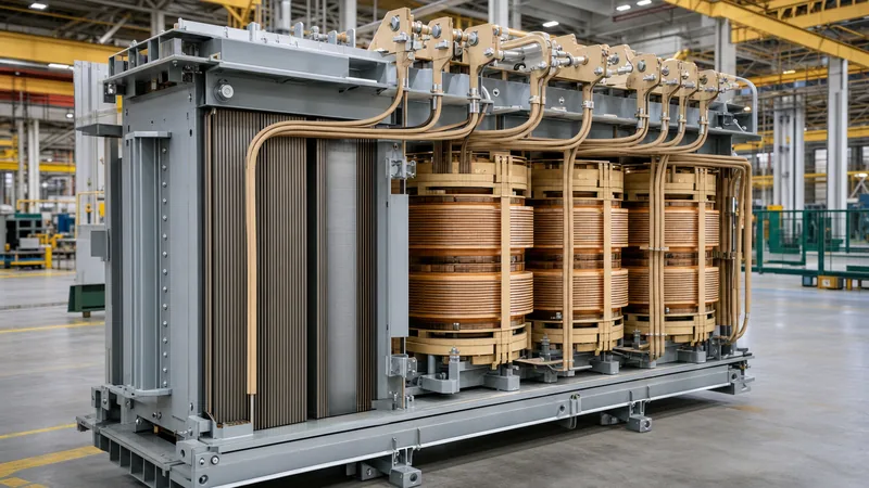
Inside an electrical transformer, the active part serves as the electromagnetic engine, comprising the laminated magnetic core clamped rigidly to withstand mechanical forces. The core provides a low-reluctance magnetic path to channel the mutual flux linking the electrical circuits. Engineers construct transformer cores from high-permeability, cold-rolled grain-oriented (CRGO) silicon steel laminations, typically graded M4, 0.23 mm, or 0.20 mm in thickness. Stacking these ultra-thin sheets with laser-scribed domain refinement drastically reduces eddy current circulation and hysteresis losses, adhering to strict no-load loss criteria in standards such as IEC 60076-1.
Modern designs employ step-lap mitered core joints cut at 45-degree angles. This continuous step-lap geometry eliminates air gaps at the corner joints, which minimises magnetising inrush current, lowers operational noise levels by 3 to 6 dB(A), and mitigates stray flux. As detailed in our comprehensive 3-phase transformer guide, high-grade core clamping frames made from structural steel channels apply uniform surface pressure (often between 1.0 and 2.0 MPa) across the core limbs and yokes. This mechanical rigidity prevents lamination vibration during energisation, ensuring that the transformer maintains stable magnetisation over a 30-to-40-year operational design life.
Transformer coil and winding architecture
A transformer coil assembly converts electric current into magnetic flux and back into voltage through conductive wire or strip arranged coaxially around the core limbs. The primary side of transformer equipment connects to the supply source, while the secondary side delivers the transformed voltage to the downstream load. Depending on the current capacity and voltage class, engineers specify electrolytic copper (with conductivity ≥ 101% IACS) or electrical-grade aluminium conductors.
Different winding configurations are deployed according to application parameters:
- Continuous disc windings: Utilised extensively for high-voltage (HV) windings above 33 kV. These discs provide superior mechanical withstand against axial short-circuit forces and optimise dielectric stress distribution under transient lightning impulses.
- Helical and spiral windings: Ideal for low-voltage (LV), high-current applications, such as the secondary side of distribution units, providing optimal cooling duct placement to dissipate resistive heat.
- Foil windings: Constructed from continuous copper or aluminium sheets across the full axial height of the coil, commonly used in cast resin dry-type transformers to eliminate layer-to-layer dielectric stresses and minimise axial short-circuit displacement forces.
The operational foundation relates directly to the fundamental transformer equation:
Vp / Vs = Np / Ns = Is / Ip
Here, V represents voltage, I represents current, and N represents the physical number of turns in the primary and secondary coils. When calculating losses and system reliability, understanding conductor cross-sections and winding arrangements helps engineers evaluate operational economics, as explored in our guide to transformer losses and total cost of ownership.
What is a transformer made of: Dielectric and insulation systems
A transformer is made of conductive metals, magnetic alloys, structural steel, and a sophisticated combination of solid and liquid dielectric materials. Electrical insulation prevents phase-to-phase flashovers, turn-to-turn short circuits, and coil-to-ground dielectric breakdowns under high electrical fields. In high-voltage transformers, insulation must endure continuous electrical stress alongside elevated operating temperatures defined by thermal classes (such as Class A 105°C, Class F 155°C, or Class H 180°C).
Solid insulation materials include high-density cellulose pressboard, thermally upgraded Kraft paper wrapped tightly around individual conductors, crepe paper tubes for flexible lead routing, and laminated wood blocks for winding clamping. In dry-type transformers, solid insulation relies on epoxy resin loaded with silica fillers, cast under strict vacuum conditions to eliminate partial discharge below 10 pC at 1.3 times rated phase-to-ground voltage. For liquid-immersed units, uninhibited or inhibited naphthenic mineral oil (meeting IEC 60296) or synthetic/natural esters (meeting IEC 61099) serve a dual purpose: providing dielectric withstand (breakdown voltage ≥ 30 kV across a standard 2.5 mm test gap) and circulating via natural or forced convection to extract winding heat. The mechanical and chemical differences between these insulation methodologies are detailed in our analysis of oil-immersed vs dry-type transformers.
Key transformer parts: Internal regulation and protection
Beyond the core and coils, auxiliary transformer parts installed inside the main tank manage voltage stability, terminal transitions, and fault detection. Voltage control is handled by tap changers, which mechanically alter the effective turns ratio on the high-voltage winding without disturbing the core flux density. These mechanisms fall into two distinct engineering classes:
- De-Energised Tap Changers (DETC): Operated manually only when the unit is disconnected from the electrical network, commonly providing a ±2 × 2.5% regulation range via rotary internal contact bridges.
- On-Load Tap Changers (OLTC): Driven by automated motor drives to shift taps under full load conditions without interrupting power, employing transition resistors or vacuum interrupters to bridge circulating currents during the contact transfer sequence.
Internal copper busbars and flexible copper braids link the winding extremities to the lower terminals of the porcelain or resin-impregnated paper (RIP) bushings. Inside conservator-equipped transformers, internal piping routes evolving fault gases upward toward the cover-mounted Buchholz relay. Furthermore, magnetic shielding shunts and laminated flux collectors line the interior tank walls to prevent stray leakage flux from inducing localised eddy-current overheating in structural steel plates during heavy loading.
Technical specifications of core internal components
Evaluating the internal build quality of power and distribution transformers requires precise alignment with international manufacturing standards. The table below outlines the core internal components, their primary engineering materials, functionality, and governing industry specifications:
| Internal Component | Primary Material | Engineering Function | Governing Standard |
|---|---|---|---|
| Magnetic Core | CRGO Silicon Steel (0.20–0.27 mm) | Channels mutual magnetic flux; minimises no-load losses | IEC 60076-1 / ASTM A876 |
| HV / LV Windings | OFHC Copper or EC-Grade Aluminium | Conducts load current; transforms voltage levels | IEC 60076-5 / IEEE C57.12.00 |
| Solid Insulation | Cellulose Pressboard & Diamond-Dotted Paper | Provides dielectric separation between turns and ground | IEC 60641 / IEC 60554 |
| Dielectric Fluid | Inhibited Mineral Oil or Natural Ester | Dielectric insulation and cooling fluid | IEC 60296 / IEEE C57.106 |
| Clamping Structure | Mild Steel Channels & Densified Wood | Maintains axial coil pressure against short circuits | ISO 898-1 |
| Tap Changer | Silver-alloy contacts with vacuum bottles | Adjusts active turns ratio to stabilise output voltage | IEC 60214-1 / IEEE C57.131 |
| Internal Leads | Paper-insulated flexible stranded copper | Connects coil extremities to bushing stems | IEC 60076-3 |
How does an electrical transformer work: Electromagnetic sequence
An electrical transformer operates on the principle of electromagnetic induction, specifically Faraday's law and Lenz's law, allowing alternating electrical energy to transfer between circuits at identical frequency without moving mechanical components. When looking at the internal interaction between the core, primary, and secondary systems, the functional sequence follows a defined physical progression:
- Primary energisation: An alternating voltage applied to the primary terminals forces an alternating excitation current through the primary winding coils.
- Core magnetisation: This primary current establishes an alternating magnetomotive force (MMF) that drives dynamic magnetic flux through the closed loop of the CRGO steel core.
- Flux linkage: The laminated core directs virtually all magnetic flux lines through its low-reluctance path, linking the turns of both the primary and secondary coils with negligible leakage.
- Electromotive force induction: The continuous time-variation of the magnetic flux induces an electromotive force (EMF) across every turn of both windings in proportion to the rate of change of flux (dΦ/dt).
- Secondary power delivery: When a closed electrical circuit is connected across the secondary terminals, the induced voltage drives a load current, supplying power transformed to the desired voltage level.
To guarantee that these internal mechanisms function flawlessly before site delivery, equipment undergoes rigorous factory verification, as outlined in our step-by-step transformer factory acceptance testing checklist.
Next steps: specifying and sourcing
When specifying internal components for substation transformers, project engineers must define exact electrical parameters in their procurement tenders. Essential data includes rated capacity (kVA or MVA), primary and secondary nominal voltages, vector group configuration, impedance (%Z), winding conductor material (copper or aluminium), and short-circuit withstand capabilities according to IEC 60076 or IEEE C57.12. Explore our engineered power transformers and rugged oil-immersed transformers built to international quality benchmarks. For project pricing, custom internal design requirements, or factory documentation, submit your specification to our engineering team via our transformer quotation portal.
Frequently asked questions
what does a transformer do
A transformer changes alternating current (AC) voltage and current levels between circuits through electromagnetic induction. It steps voltage up for long-distance transmission or steps it down for safe industrial, commercial, and residential distribution, keeping frequency constant.
how does a transformer work
A transformer works by passing alternating current through a primary coil to generate an alternating magnetic field inside a steel core. This expanding and collapsing magnetic flux links with a secondary coil, inducing an output voltage proportional to the turns ratio.
what is inside a transformer
Inside a transformer is the active assembly, which consists of a laminated silicon steel core, insulated primary and secondary copper or aluminium windings, and structural clamping frames. In oil-filled designs, the tank also contains dielectric fluid, tap changers, and internal lead connections.
what does a transformer look like
Externally, an electrical transformer looks like a heavy steel enclosure or tank fitted with cooling radiators, high-voltage ceramic or resin bushings on top, and an oil conservator tank. Internally, it resembles stacked cylindrical wire coils wrapped tightly around vertical steel core limbs.
what is a transformer made of
A transformer is made of high-permeability cold-rolled grain-oriented silicon steel for the core, electrolytic copper or aluminium for the windings, and structural steel for clamping. Insulation materials comprise cellulose pressboard, Kraft paper, and dielectric liquid or epoxy casting resin.
what does a power transformer do
A power transformer transfers bulk electrical energy across transmission and sub-transmission networks, stepping voltages up to levels like 110 kV, 220 kV, or higher to reduce I²R transmission line losses. It acts as the primary voltage conversion node in transmission substations.
Tags: transformer transformers internal components transformer parts transformer coil what is inside a transformer


