Key takeaways
- A three winding transformer is specified by three pairwise impedances, Z12, Z13 and Z23, each measured with the third winding open and stated on a common MVA base.
- Star equivalent branches are Z1 = (Z12 + Z13 − Z23) / 2 and similar; one branch is often near zero or slightly negative, which is physically normal.
- Typical capacity ratios are 100/100/100 or 100/100/50, and the sum of the two output loadings must not exceed the primary rating.
- A delta tertiary winding provides a path for triplen harmonics and zero-sequence current in YNyn transformers and autotransformers.
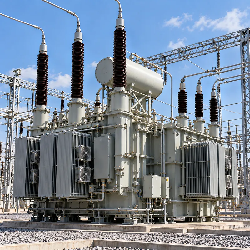
- Three-winding 110 kV units, for example 110/35/10 kV, let one substation transformer feed both subtransmission and distribution networks.
Quick answer: A three winding transformer has three windings per phase on one core, typically HV, MV and LV, so a single unit can link three voltage levels or supply two loads from one source. A third winding may also be a delta tertiary that stabilizes the neutral and carries third-harmonic and zero-sequence currents. Analysis uses a star equivalent of three pairwise impedances.
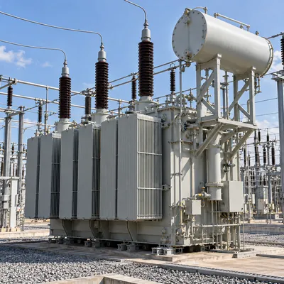
Most transformers have two windings. Add a third, and one machine can do the job of two: step 110 kV down to both 35 kV and 10 kV, feed a station service and reactive compensation bus, or give a wye-wye transformer the delta path it needs for stable operation.
This guide is for utility and industrial engineers evaluating a three winding power transformer for a substation, generation plant or large industrial site. It explains configurations, the tertiary winding, the impedance model with a worked example, loading rules, protection, and what to include in an RFQ.
What Is a Three Winding Transformer?
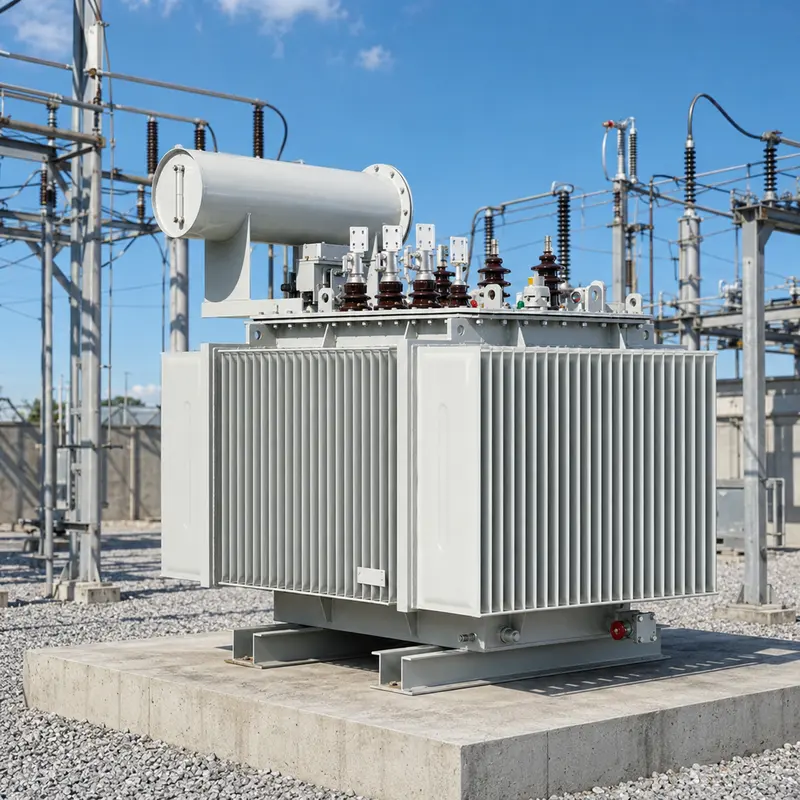
A three winding transformer is a transformer with three separate windings per phase, all linked by the same magnetic core, each connected to a different circuit or performing a different function. The windings are usually named primary (HV), secondary (MV or LV) and tertiary. The informal term 3 coil transformer describes the same arrangement in single-phase equipment.
Because all three windings share one flux, the voltage on each follows its turns: V1 : V2 : V3 = N1 : N2 : N3. Power can flow from any winding to the other two, so the unit behaves as three interconnected two-winding transformers sharing a core.
Common configurations include:
- Three voltage levels: 110/35/10 kV, 132/33/11 kV or 220/110/35 kV substation transformers, each winding feeding its own network.
- Generator or plant service: one HV winding and two LV windings to connect two generators, or a generator and an auxiliary system.
- Stabilizing tertiary: a delta winding, often not brought out to terminals, inside a YNyn transformer or autotransformer.
- Split or double secondary: two identical LV windings with high impedance between them, used for converters, PV inverters and multi-pulse rectifiers; see our rectifier transformer guide.
Vector groups follow the usual notation, for example YNyn0d11 for a star-star transformer with a delta tertiary, or YNd11d11 for a double-secondary unit; our transformer vector groups explained article covers the clock notation.
What Does a Tertiary Winding Do?
A tertiary winding is the third winding of a transformer, usually lower in voltage and rating than the main windings, provided either to supply a separate load or to improve the electrical behaviour of the transformer. When connected in delta, it performs several functions at once:
- Third-harmonic path. Core magnetising current contains a third-harmonic component. In a wye-wye transformer without a delta, that current cannot flow freely and third-harmonic voltage appears in the phase voltages. A closed delta lets the third harmonic circulate, keeping phase voltages sinusoidal.
- Neutral stabilization. With unbalanced single-phase loads on a wye-wye bank, the neutral can shift. The delta tertiary supplies the zero-sequence ampere-turns that hold it in place.
- Zero-sequence impedance control. The delta lowers zero-sequence impedance, increasing ground fault current available for protection. This matters for autotransformers, covered in our autotransformer guide.
- Auxiliary supply. A brought-out tertiary at, for example, 10.5 kV or 13.8 kV can feed station service transformers, shunt reactors or capacitor banks.
A stabilizing tertiary that is not loaded is often rated around one-third of the main winding rating, but the true requirement comes from the maximum zero-sequence current it must carry during an external ground fault, and from short-circuit withstand. Because a tertiary is low-voltage and low-impedance relative to the main windings, short-circuit forces on it can be severe; unloaded tertiaries are sometimes left with one corner of the delta brought out for testing and CT installation only.
An alternative to a tertiary for providing a ground source is a separate zigzag unit; our grounding transformer guide compares the two.
Three Winding Transformer Impedance: Star Equivalent
A two-winding transformer has one leakage impedance. A three winding transformer has three, one for each pair of windings, measured by short-circuit tests with the third winding open:
Z12: HV to MV, LV openZ13: HV to LV, MV openZ23: MV to LV, HV open
For load flow and fault studies these are converted to a star (T) equivalent, with one branch per winding joined at a fictitious star point:
Z1 = (Z12 + Z13 − Z23) / 2Z2 = (Z12 + Z23 − Z13) / 2Z3 = (Z13 + Z23 − Z12) / 2
All three pairwise values must be on the same MVA base before conversion. Test reports often state Z23 on the rating of the smaller winding, so convert first using Z(new) = Z(old) × S(new base) / S(old base). Our transformer equivalent circuit article explains the two-winding model this builds on, and the transformer impedance calculations guide covers base conversion.
Worked example: 31.5 MVA, 110/35/10.5 kV, step-down arrangement. Test values on 31.5 MVA base: Z12 = 10.5%, Z13 = 17.5%, Z23 = 6.5%.
Z1 = (10.5 + 17.5 − 6.5) / 2 = 10.75%Z2 = (10.5 + 6.5 − 17.5) / 2 = −0.25%Z3 = (17.5 + 6.5 − 10.5) / 2 = 6.75%
The small negative Z2 is not an error. It arises because the MV winding sits physically between HV and LV, and it simply means the MV branch adds almost nothing to impedance between the star point and the MV bus. For a bolted fault on the 10.5 kV bus fed from an infinite 110 kV source, the path is Z1 + Z3 = 17.5%, so fault current is IFL(10.5 kV) / 0.175, with IFL = 31.5 MVA / (√3 × 10.5 kV) = 1,732 A, giving about 9.9 kA.
Ratings, Capacity Ratios and Loading
Each winding of a three winding transformer has its own rated power, and the ratios between them form part of the specification.
| Capacity ratio (HV/MV/LV) | Meaning | Typical use |
|---|---|---|
| 100/100/100 | Each winding can carry full rating | Substations where either output may carry full load |
| 100/100/50 | LV winding at half rating | MV main load with smaller LV distribution |
| 100/50/100 | MV winding at half rating | LV main load with limited MV interconnection |
| 100/100/33 (stabilizing) | Unloaded or lightly loaded delta tertiary | YNyn or autotransformer stabilization |
Loading rules are straightforward but often overlooked:
- The primary carries the phasor sum of the two output loads, so
S1 ≤ S1(rated)limits the combination even when each output is within its own rating. - Each output winding must stay within its own rating at its own power factor.
- Temperature rise is governed by total losses, which depend on how load is shared, so a 100/100/50 transformer loaded 100% on MV and 50% on LV at the same time would exceed the primary rating.
Example: a 31.5 MVA, 100/100/50 unit supplies 22 MVA at 0.9 PF on the 35 kV winding and 12 MVA at 0.85 PF on the 10.5 kV winding. Real power is 22 × 0.9 + 12 × 0.85 = 30.0 MW; reactive power is 22 × 0.436 + 12 × 0.527 = 15.9 Mvar. Primary load is √(30.0² + 15.9²) ≈ 34.0 MVA, above 31.5 MVA, so this combination is not permissible even though 22 MVA and 12 MVA are each within their winding ratings (31.5 and 15.75 MVA). Loading guides such as IEC 60076-7 and IEEE C57.91 apply to each winding's hot spot.
Three Winding vs Two Winding vs Autotransformer
A three winding power transformer is not always the cheapest way to serve three voltage levels. Compare options on the whole substation, not just the transformer.
| Option | Advantages | Drawbacks |
|---|---|---|
| One three-winding transformer | Single foundation, fewer HV bays, lower total losses than two units, compact substation | Outage removes both outputs; interdependent impedances; heavier single unit to transport |
| Two two-winding transformers (HV/MV and HV/LV) | Independent outages and impedances; simpler protection | More HV switchgear bays, larger site, higher total cost |
| Two transformers in cascade (HV/MV then MV/LV) | Standard designs; LV unit can be distribution class | LV load passes through two transformations, higher losses |
| Autotransformer with tertiary | Smallest for ratios near 1:1, e.g., 220/110 kV, tertiary feeds auxiliary loads | No isolation between HV and MV; high fault levels |
Three winding designs are common in 110 kV substations that supply both 35 kV subtransmission and 10 kV distribution, in generating stations with two generator windings, and in industrial plants with large MV motor loads plus distribution at a second voltage. Voltage control usually relies on an on-load tap changer on the HV winding, with off-circuit taps on the MV winding when the two outputs must be regulated separately; our load tap changer guide explains placement.
Protection of Three Winding Transformers
Protection must cover three sets of terminals and the interactions between them:
- Differential protection (87T): a three-restraint differential relay with CTs on all three windings, compensated for ratio and vector group. Harmonic restraint handles inrush.
- Overcurrent backup (51) per winding, coordinated so that a fault on one output bus does not trip the other output.
- Restricted earth fault (64REF) on grounded wye windings for sensitive detection of winding-to-ground faults near the neutral.
- Tertiary protection: an unloaded delta tertiary is often protected by a single CT inside the delta or a residual voltage scheme; a loaded tertiary needs its own overcurrent protection.
- Mechanical protection: Buchholz or gas relay, pressure relief, oil and winding temperature indicators, as for any oil-immersed power transformer.
Fault studies should include low-impedance paths between the two output windings: a fault on the MV bus is fed both from HV and, through the star equivalent, can draw back-feed from LV if there are generators or motors connected. Our substation transformer engineering guide discusses protection scope for 35–110 kV units. Relay settings should be reviewed whenever capacity ratios, tap positions or grounding arrangements change, because each affects the current balance seen by the differential element.
Next Steps: Specifying and Sourcing
A three winding transformer RFQ needs more data than a two-winding one. Include:
- Rated power of each winding and the capacity ratio, e.g., 31.5/31.5/15.75 MVA.
- Voltages, tap ranges and whether on-load or off-circuit tap changing applies to each winding.
- Vector group, e.g., YNyn0d11, and whether the tertiary is brought out and loaded.
- All three pairwise impedances, the base on which each is stated and the winding arrangement (step-up or step-down).
- Neutral grounding of each wye winding and zero-sequence impedance requirements.
- Cooling class (ONAN, ONAF), insulation levels, loss evaluation figures and noise limits.
- Standards: IEC 60076 or IEEE C57.12.00, plus utility specifications.
MARS manufactures oil-immersed power transformers up to 31,500 kVA and 110 kV class, designed to IEC 60076 with ANSI/IEEE, GB and GOST variants at 50 or 60 Hz, together with matching substation equipment and switchgear. Every unit is routine-tested, FAT witness is welcome, and typical lead time for power transformers is 60–90 days. Send your single line and winding data through the quote page for engineering review.
Ask for impedance test results on all three winding pairs in the routine test report, stated on a common base, so your load flow and fault models match the delivered unit.
Frequently asked questions
Why use a three winding transformer?
A three winding transformer lets one unit connect three voltage levels or supply two separate loads from one source, saving HV switchgear bays, foundation space and losses compared with two separate transformers. It can also include a delta tertiary that stabilizes the neutral, carries third-harmonic current and provides an auxiliary supply for station service or reactive compensation.
What is the purpose of a tertiary winding?
A tertiary winding, usually delta-connected, provides a closed path for third-harmonic magnetising current, stabilizes the neutral under unbalanced loads, lowers zero-sequence impedance for ground fault protection and can supply auxiliary loads such as station service transformers, reactors or capacitor banks. It is common in wye-wye transformers and autotransformers.
How do you calculate the impedance of a three winding transformer?
Measure or obtain the three pairwise impedances Z12, Z13 and Z23 on a common MVA base, then convert to a star equivalent: Z1 = (Z12 + Z13 − Z23)/2, Z2 = (Z12 + Z23 − Z13)/2 and Z3 = (Z13 + Z23 − Z12)/2. Fault current between two windings uses the sum of their two branch impedances.
Can a star equivalent impedance be negative?
Yes. One branch of a three winding transformer's star equivalent can be zero or slightly negative, typically for the winding placed physically between the other two. It is a mathematical result of the model, not a physical negative impedance, and the pairwise sums, which correspond to measurable quantities, are always positive.
What is a 100/100/50 three winding transformer?
A 100/100/50 three winding transformer has a primary and secondary rated at full nameplate power and a third winding rated at half. The combined load on the two output windings must still not exceed the primary rating, so the third winding's lower rating suits a smaller distribution or auxiliary load.
Is a three winding transformer the same as a three phase transformer?
No. Three phase refers to the number of phases, while three winding refers to the number of windings per phase. A three phase, two winding transformer has six windings in total, while a three phase, three winding transformer has nine. A single-phase transformer can also have three windings, often called a 3 coil transformer.
Written and reviewed by the MARS application engineering team in Shanghai, who specify and test transformers, switchgear, substations and battery storage for projects in 40+ countries. Last updated .
Tags: three winding transformer 3 winding transformer tertiary winding three winding power transformer 3 coil transformer