Key takeaways
- Only the fraction (1 − VL/VH) of an autotransformer's throughput is transformed magnetically; a 132/66 kV unit transforms just half its rated MVA.
- Savings are largest for ratios near 1:1 and fade beyond about 3:1, which is why autotransformers dominate grid interconnections such as 345/138 kV.
- Per-unit impedance is lower than an equivalent two-winding design by the co-ratio, so autotransformer fault currents are higher and need checking.
- Autotransformers have no galvanic isolation, so a series-winding fault can expose the low-voltage side to high-voltage stress.
- Three-phase wye autotransformers normally need a solidly grounded neutral and often a delta tertiary for zero-sequence and third-harmonic paths.
Quick answer: An autotransformer is a transformer with one winding per phase that is shared by the primary and secondary circuits, with the output taken from a tap. Part of the power passes by direct conduction, so it is smaller, lighter and more efficient than a two-winding transformer for ratios close to 1:1, but it provides no galvanic isolation between input and output.
Autotransformers sit at two extremes of the power industry. At the small end they are the variable bench supplies in every test lab and the reduced-voltage starters on large pumps. At the large end they are the interbus transformers that tie 500 kV, 345 kV and 230 kV networks together. The same principle, a single tapped winding, explains both.
This guide is for engineers and buyers who need to decide between an autotransformer and a conventional two-winding transformer. It covers the working principle, the co-ratio math that determines size and cost, practical examples, protection and grounding issues, and what to put in a specification.
What Is an Autotransformer?
An autotransformer is a transformer in which the input and output circuits share part of the same winding, so they are connected both magnetically and electrically. Instead of two separate coils per phase, there is one continuous winding with a tap. The part of the winding common to both circuits is called the common winding; the remainder, which carries only the higher-voltage current, is the series winding.
In a step-down auto transformer, the full high voltage is applied across the whole winding and the output is taken between the tap and the common end. In a step-up connection the roles reverse. Because the windings are linked, the voltage ratio still follows the turns ratio, VH / VL = NH / NL, exactly as in any transformer (see our transformer turns ratio formula guide).
What makes it different is how power flows. In a two-winding transformer all power is transferred through the core by induction. In an autotransformer some power flows straight through the winding by conduction and only the remainder is transformed magnetically. That single fact explains why the autotransformer is smaller, cheaper and more efficient for modest ratios, and why it gives up isolation.
Common forms include:
- Fixed-ratio single-phase and three-phase autotransformers for voltage matching, such as 480 V to 600 V or 400 V to 690 V.
- Variable autotransformers (variacs) with a sliding brush on a toroidal winding, used in labs and test benches.
- Starting autotransformers for reduced-voltage motor starting.
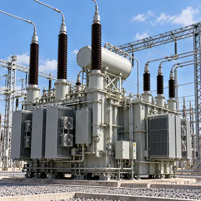
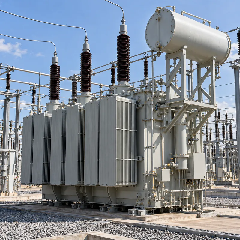
- Large power autotransformers, usually with on-load tap changers and a delta tertiary winding, for EHV and HV interconnections.
How an Autotransformer Works: Conduction Plus Induction
To see how an autotransformer works, consider a step-down unit supplying load current IL at voltage VL from a source at VH. Ignoring losses, input and output apparent power are equal: VH × IH = VL × IL, so IH = IL × VL / VH.
The series winding carries IH. At the tap, the load current IL is made up of IH arriving from the series winding plus the common-winding current IC = IL − IH. Because IC is the difference of two currents, the common winding can be built with a smaller conductor than a two-winding secondary would need.
The power split is:
- Conducted power (passes straight through):
S × VL / VH - Transformed power (passes through the core):
S × (1 − VL / VH)
The term (1 − VL / VH) is the co-ratio. The physical size, core and copper of an autotransformer correspond to its transformed power, often called the equivalent two-winding rating. The table shows how quickly the advantage falls as the ratio grows.
| Voltage ratio VH/VL | Co-ratio (1 − VL/VH) | Equivalent two-winding size | Typical application |
|---|---|---|---|
| 1.1 : 1 | 0.09 | 9% of throughput | Voltage boosting, buck-boost |
| 1.25 : 1 | 0.20 | 20% | 480 V to 600 V matching |
| 1.5 : 1 | 0.33 | 33% | 345/230 kV interconnection |
| 2 : 1 | 0.50 | 50% | 132/66 kV, 230/115 kV |
| 3 : 1 | 0.67 | 67% | Marginal benefit |
| 10 : 1 | 0.90 | 90% | Not economic; use two-winding |
Reduced material also means lower no-load and load losses for the same throughput, which improves efficiency (see transformer efficiency).
Worked Example: Sizing a 132/66 kV Autotransformer
A utility needs to transfer 60 MVA between a 132 kV and a 66 kV network. Compare an autotransformer with a two-winding unit.
Step 1, co-ratio: 1 − 66 / 132 = 0.5. The equivalent two-winding rating is 0.5 × 60 = 30 MVA. The autotransformer is built roughly like a 30 MVA two-winding transformer while carrying 60 MVA.
Step 2, line currents using I = S / (√3 × V):
- HV side:
60,000,000 / (1.732 × 132,000) = 262 A - LV side:
60,000,000 / (1.732 × 66,000) = 525 A
Step 3, winding currents. The series winding carries the HV current, 262 A. The common winding carries 525 − 262 = 263 A. A two-winding transformer would need an LV winding rated for the full 525 A.
Step 4, impedance. Suppose the design has an impedance equivalent to 10% on its 30 MVA two-winding base. Referred to the 60 MVA throughput base, the per-unit impedance is about 10% × 0.5 = 5%. A comparable two-winding transformer is typically specified around 10–12%. Lower impedance improves regulation but raises through-fault current, roughly doubling it in this case, so downstream breakers and the transformer's own short-circuit withstand per IEC 60076-5 or IEEE C57.12.00 must be checked. Our transformer impedance calculations guide shows the base conversion in detail.
The same math applies at low voltage. Boosting 208 V to 230 V for a 20 kVA load has a co-ratio of 1 − 208/230 = 0.096, so a 2 kVA transformer connected as an autotransformer does the job, which is exactly the principle behind the buck-boost transformer.
Examples of Autotransformers in Real Systems
The most searched question is for an example of an autotransformer. Here are the ones engineers meet most often:
- Variable autotransformer (variac): a toroidal winding with a carbon brush that slides over the exposed turns, giving a smoothly adjustable output from zero to slightly above input voltage. Used for test benches, heater control and slowly bringing up repaired equipment.
- Autotransformer motor starter: taps at 50%, 65% and 80% reduce starting voltage on large induction motors. At the 65% tap, motor current is 65% of locked-rotor current, but line current falls to about 0.65² = 42%, and torque also falls to about 42%. Our motor starter types guide compares this with star-delta and soft starters.
- Buck-boost transformers: small two-winding units field-connected as autotransformers to correct 5–20% voltage differences.
- Grid interconnection autotransformers: 500/230 kV, 345/138 kV and 400/220 kV units linking transmission networks, typically with a delta tertiary and on-load tap changer.
- Railway 2 × 25 kV systems: autotransformers along the line split supply between catenary and feeder to reduce voltage drop and interference.
- Generator and industrial voltage matching: 400 V to 690 V or 480 V to 600 V for equipment imported from another voltage system.
A note on searches for an automotive transformer: the classic vehicle ignition coil is effectively an autotransformer-connected step-up coil, with primary and secondary sharing a common connection, converting 12 V pulses to tens of kilovolts at the spark plug. Modern coil-on-plug units use the same principle. These are specialist automotive parts, unrelated to power distribution equipment.
Autotransformer vs Transformer: Which Should You Use?
The autotransformer vs transformer decision is a trade between size and cost on one side and isolation and fault behaviour on the other. Our isolation transformer guide explains why galvanic separation matters for safety and noise.
| Criterion | Autotransformer | Two-winding transformer |
|---|---|---|
| Windings per phase | One, tapped | Two, separate |
| Galvanic isolation | None | Yes |
| Size and weight for ratio near 1:1 | Much smaller | Full size |
| Losses | Lower for same throughput | Higher |
| Per-unit impedance | Lower; higher fault current | Freely chosen |
| Vector group options | Essentially Yy (YNa0), no phase shift | Any, e.g., Dyn11, YNd1 |
| Neutral grounding | Common neutral; normally solid grounding | Independent on each side |
| Separately derived system (NEC 250.30) | No | Yes |
| Best ratio range | Up to about 2–3:1 | Any |
Choose a two-winding transformer when you need a large voltage ratio (for example 11 kV to 400 V), a phase shift such as delta-wye to block zero-sequence current, a new grounded neutral, isolation for safety or noise, or independent grounding on each side. Choose an autotransformer when both networks are already solidly grounded, the ratio is modest, and the savings in cost, weight and losses justify the higher fault level. Transport limits can also tip the decision: at transmission ratings, an autotransformer may be shippable where an equivalent two-winding unit would exceed road or rail weight limits.
Protection, Grounding and Tertiary Windings
Because the circuits are connected, an autotransformer imposes specific design rules.
Grounding. A three-phase wye autotransformer has one neutral common to both systems. It is normally solidly grounded; if it were ungrounded, a ground fault on one side would shift the neutral and stress the other. Both networks must therefore be effectively grounded systems.
Tertiary winding. Large three-phase autotransformers commonly include a delta-connected tertiary. It provides a path for third-harmonic magnetising current, stabilises the neutral, reduces zero-sequence impedance and can supply station service or reactive compensation. Our three winding transformer guide covers tertiary sizing and the three-winding equivalent circuit.
Surge and fault exposure. If the series winding fails open or a fault bridges the series winding, the LV network sees HV potential. Surge arresters are required on both sides, and insulation coordination must consider transferred surges.
Differential protection. Since there is no phase shift, differential (87T) protection is simpler to compensate, but schemes must handle the common neutral; high-impedance restricted earth fault or current-balance schemes on the common winding are typical. Energisation inrush still applies, as explained in our transformer inrush current guide.
Tap changing. On-load tap changers can be placed at the line end of the series winding or at the neutral end; neutral-end tapping reduces insulation requirements but changes the volts-per-turn and therefore core flux across the tap range. See our load tap changer guide.
Next Steps: Specifying and Sourcing
Before issuing an RFQ, confirm that an autotransformer is permitted by the utility or plant standard and that both systems are effectively grounded. Then specify:
- Throughput rating (kVA or MVA), voltages and whether step-up or step-down.
- Required impedance on throughput base and maximum through-fault current that downstream equipment can accept.
- Tap range and whether off-circuit or on-load tap changing is needed.
- Tertiary winding: required or not, rating, whether loaded or stabilising only, and whether it is brought out.
- Cooling class, insulation levels (BIL), standards (IEC 60076 or IEEE C57.12.00) and frequency (50 or 60 Hz).
- Losses at specified load points if the purchase is evaluated on total cost of ownership.
MARS manufactures power transformers up to 31,500 kVA and 110 kV class, together with oil-immersed and dry-type distribution transformers, designed to IEC 60076 with ANSI/IEEE, GB and GOST variants. For many industrial and utility projects at these ratings, a two-winding or three-winding design gives the isolation, vector group and grounding flexibility the system needs; MARS engineers can review your single line and confirm the configuration that fits. Lead time for power transformers is typically 60–90 days, routine tests are performed on every unit and FAT witness is welcome. Send your data through the quote page.
Frequently asked questions
What is an autotransformer used for?
An autotransformer is used where a modest voltage change is needed without isolation: interconnecting transmission networks such as 345/138 kV, matching equipment voltages like 480 V to 600 V, boosting or bucking supply voltage, reduced-voltage starting of large motors, and variable laboratory supplies. It is chosen because it is smaller, lighter and more efficient than a two-winding transformer at ratios near 1:1.
What is the main disadvantage of an autotransformer?
The main disadvantage is the lack of galvanic isolation. Input and output share a winding, so faults, surges and ground potentials can transfer between systems, and a failure of the series winding can expose the low-voltage side to high voltage. Autotransformers also have lower per-unit impedance, which increases fault current, and offer no phase shift or independent neutral grounding.
Why is an autotransformer more efficient?
An autotransformer is more efficient because only part of the power, the co-ratio fraction (1 minus VL/VH), is transformed magnetically. The rest passes by conduction. That means less core and copper for the same throughput, so no-load and load losses are lower. The benefit is greatest for ratios close to 1:1 and diminishes as the ratio increases.
Can an autotransformer be used as an isolation transformer?
No. An autotransformer cannot provide isolation because its primary and secondary circuits are electrically connected through the shared winding. Any application requiring galvanic separation, such as medical equipment, safety extra-low voltage, noise suppression or creating a new separately derived system under NEC 250.30, needs a two-winding isolation transformer with separate primary and secondary coils.
What is a variac?
A variac is a variable autotransformer: a single winding on a toroidal core with a carbon brush that slides across exposed turns. Rotating the knob changes the tap position, giving a continuously adjustable output from zero to slightly above input voltage. Variacs are used for test benches and heater control but provide no isolation from the supply.
How do you calculate the rating of an autotransformer?
Multiply the throughput power by the co-ratio, (1 − VL/VH), to get the equivalent two-winding rating that determines physical size. For example, a 60 MVA, 132/66 kV autotransformer has a co-ratio of 0.5, so it is built like a 30 MVA two-winding transformer. Winding currents follow from the throughput: series winding carries HV current, common winding carries the difference.
Written and reviewed by the MARS application engineering team in Shanghai, who specify and test transformers, switchgear, substations and battery storage for projects in 40+ countries. Last updated .
Tags: autotransformer auto transformer what is an autotransformer autotransformer vs transformer example of autotransformer