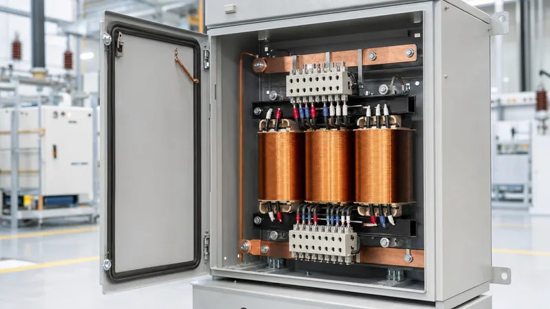
Key takeaways
- A buck boost transformer is an isolating dry-type transformer wired as an autotransformer to raise or lower distribution voltage by 5% to 20%.
- Connected as an autotransformer, a unit can supply load kVA ratings 5 to 20 times higher than its rated isolating nameplate kVA.
- A single phase buck boost transformer can be banked in pairs for open-delta or triplets for wye configurations to handle three-phase industrial loads.
- Buck boosters do not regulate fluctuating utility grids; they deliver a fixed percentage voltage change based on winding turns ratios.
- National Electrical Code (NEC) Article 450-4 explicitly governs the overcurrent protection and installation rules for autotransformer connections.
Quick answer: A buck boost transformer is a standard single-phase dry-type distribution transformer designed to be field-connected as an autotransformer, providing an economical method to raise (boost) or lower (buck) supply voltage by 5% to 20%. It is engineered to eliminate chronic undervoltage or overvoltage issues for motor loads, HVAC equipment, and industrial automation without requiring expensive line replacement.
In industrial power distribution, nominal utility voltages often deviate from load nameplate ratings. A facility operating on a 208 V supply might install imported machinery engineered for 230 V, or high impedance feeder runs may drop nominal 480 V lines down to 440 V at the machine terminals. Rather than replacing the primary power feed or installing a costly full-sized isolation transformer, electrical contractors routinely specify compact buck boosters. Sometimes colloquially misheard as a bucket transformer, this robust hardware offers an exceptionally cost-effective solution when properly engineered. To understand how these units compare with full-sized step-up designs, see our step-up transformer engineering guide.
What is a Buck Boost Transformer and How Does It Work?
A buck boost transformer operates by adding (boosting) or subtracting (bucking) a secondary winding voltage to or from the primary line voltage through conductive and magnetic coupling. Unlike standard isolating transformers where the primary and secondary circuits remain electrically segregated, field-interconnecting the windings configures the unit as an autotransformer. In this configuration, the input power passes directly through the primary winding while the secondary winding is placed in series with the load.
When wired to boost, the secondary voltage adds in phase to the incoming line voltage. For instance, when stepping up a 208 V line to 230 V, the secondary winding supplies the required 22 V differential. Conversely, in a transformer buck connection, the secondary polarity is reversed relative to the line, subtracting that same voltage increment to protect equipment from overvoltage stress. Because the unit only handles the differential voltage rather than the total circuit power, the physical core and coil assembly can be substantially smaller than a conventional isolation transformer. For standard isolation principles, review our guide to dry-type transformers.
Autotransformer kVA Multiplication Advantage
The core economic benefit of buck boosters is their remarkable kVA multiplication factor when connected in autotransformer arrangements. The transformer core only transforms the "bucked" or "boosted" portion of the electrical energy, while the bulk of the power flows conductively through the series connection. Consequently, a small insulating transformer with a physical nameplate rating of only 1 kVA can handle a motor or heating load of 10 kVA to 20 kVA.
The mathematical relationship governing autotransformer capacity is defined by the input-to-output voltage ratio:
Load kVA = Nameplate kVA × (Output Voltage / Differential Voltage)
For example, consider a 1.0 kVA single phase buck boost transformer featuring 120 V primary and 12 V secondary windings. The secondary winding is rated to carry 83.33 A (1000 VA / 12 V = 83.33 A). When connected in series-aiding configuration on a 120 V line, the output voltage becomes 132 V (120 V + 12 V). The total load capacity supported by this 1 kVA unit becomes:
Load kVA = (132 V × 83.33 A) / 1000 = 11.0 kVA
This represents an 11-fold increase in usable load handling capacity relative to the physical iron and copper footprint of the unit, drastically reducing capital expenditure, enclosure size, and structural mounting requirements.
Wiring Configurations for Single Phase and Three Phase Systems
Wiring a boost transformer requires strict adherence to polarity markings (typically designated H1, H2 for high-voltage primaries and X1, X2, X3, X4 for low-voltage secondaries). Miswiring leads directly to an unintended buck operation or an outright short circuit across the supply lines. Understanding these schematic conventions is detailed in our transformer symbol and schematic guide.
Three-phase systems require multiple single-phase units banked together, configured depending on whether the system is a four-wire wye or three-wire delta distribution:
- Three-Phase Wye Bank (Four-Wire): Employs three identical single-phase transformers. Each primary winding is connected between one phase conductor and the common system neutral, while the secondary winding is placed in series with that phase line. This delivers balanced line-to-neutral and line-to-line voltage correction across all three phases.
- Open-Delta Bank (Three-Wire): Uses only two single-phase buck boost transformers to balance a three-phase delta load. While saving initial equipment cost, the maximum allowable bank capacity is derated to 86.6% of the sum of the individual autotransformer capacities.
- Closed-Delta Bank: Rarely recommended for buck-boost connections due to internal circulating currents caused by minor phase angle shifts and winding impedance mismatches.
Buck Boost Transformer Sizing and Selection Table
Accurate sizing requires determining line voltage, desired load voltage, total load amperage, and operational phase configuration. The table below presents standard single-phase autotransformer combinations based on universal dual-voltage windings (120/240 V primary, 12/24 V or 16/32 V secondary) compliant with IEEE C57.12.00 and applicable NEMA standards.
| Nominal Input (V) | Desired Output (V) | Correction Factor (%) | Required Secondary (V) | Physical Nameplate (kVA) | Max Load Rating (kVA) | Max Load Current (A) |
|---|---|---|---|---|---|---|
| 208 | 230 | +10.5% (Boost) | 24 (Series) | 0.50 | 4.79 | 20.8 |
| 208 | 230 | +10.5% (Boost) | 24 (Series) | 1.00 | 9.58 | 41.6 |
| 208 | 230 | +10.5% (Boost) | 24 (Series) | 2.00 | 19.16 | 83.3 |
| 240 | 208 | -13.3% (Buck) | 32 (Series) | 0.75 | 4.87 | 23.4 |
| 240 | 208 | -13.3% (Buck) | 32 (Series) | 1.50 | 9.75 | 46.9 |
| 460 | 480 | +4.3% (Boost) | 20 (Parallel) | 1.00 | 24.00 | 50.0 |
| 480 | 456 | -5.0% (Buck) | 24 (Series) | 2.00 | 38.00 | 83.3 |
To compute precise requirements for distribution setups beyond standard values, reference our detailed tutorial on how to size a distribution transformer.
Step-by-Step Procedure to Calculate Required Transformer Sizing
Sizing an autotransformer configuration requires calculating the precise current demanded by the load and matching it to the secondary full-load ampacity of the unit. Follow this four-step engineering workflow:
- Determine the Voltage Differential: Measure the actual incoming supply voltage ($V_{in}$) under peak load conditions and identify the rated equipment operating voltage ($V_{out}$). Calculate the delta: $\Delta V = |V_{out} - V_{in}|$.
- Determine Full Load Amperage: Obtain the maximum continuous load current ($I_{load}$). For three-phase systems, calculate $I_{load} = Load\ VA / (V_{out} \times \sqrt{3})$. For single-phase loads, calculate $I_{load} = Load\ VA / V_{out}$.
- Calculate the Required Transformer VA: Multiply the voltage differential by the full load current: $Transforming\ VA = \Delta V \times I_{load}$. This value defines the physical nameplate rating required for the transformer core.
- Select Standard Catalog Rating: Select a standard physical nameplate unit whose rated secondary winding current exceeds $I_{load}$. Always apply a 125% continuous duty multiplier if the load operates continuously for three hours or more in compliance with standard electrical safety codes.
Critical Limitations: When NOT to Use Buck Boosters
A buck boost transformer is an effective engineering solution, but applying it incorrectly creates severe operational and safety hazards. Electrical engineers must avoid specifying buck-boost units under the following operational conditions:
First, they must never be deployed as active voltage regulators. Buck boosters feature fixed winding turns ratios. If utility grid voltage fluctuates wildly between 190 V and 220 V throughout the day, a 10% boost connection will merely shift that fluctuating window upward to 209 V – 242 V. Sensitive electronics requiring tight ±2% regulation necessitate a servo-controlled or solid-state voltage stabilizer instead.
Second, buck-boost autotransformers do not provide electrical circuit isolation. Because the secondary winding connects directly to the incoming circuit, noise, common-mode harmonics, and transient spikes traverse straight through to the load. Where local electrical safety codes or sensitive medical devices require an isolated neutral ground plane, full dry-type transformers or heavy-duty power transformers must be installed. Finally, NEC Section 450-4 explicitly prohibits using autotransformers to create a 120 V neutral feed from a 240 V ungrounded system unless specific grounding conditions are satisfied.
Next steps: specifying and sourcing
Specifying the optimal buck-boost arrangement requires defining your exact measured supply voltage, equipment nameplate voltage, continuous running current, operating frequency (50 Hz or 60 Hz), and environmental enclosure rating (such as NEMA 3R or IP54). Our factory manufactures premium, copper-wound isolating transformers and autotransformers engineered to international standards including IEC 60076 and IEEE C57. Explore our high-efficiency dry-type distribution transformers and modular HV/LV switchgear solutions for comprehensive industrial infrastructure. Submit your technical project specifications to our electrical application engineering department on our transformer quotation page to receive custom sizing confirmation and factory-direct pricing within 24 hours.
Frequently asked questions
What is the difference between an autotransformer and a buck boost transformer?
A buck boost transformer is manufactured as an isolated four-winding transformer that is field-wired as an autotransformer. An autotransformer is an electrical circuit topology where the input and output share a single continuous conductive winding.
Can a buck boost transformer regulate fluctuating voltage?
No, a buck boost transformer cannot regulate fluctuating voltage because it has a fixed turn ratio. It delivers a permanent, fixed percentage voltage boost or buck regardless of fluctuations in the input utility supply.
Why is a buck boost transformer smaller than a standard isolation transformer?
It is smaller because it only converts the voltage difference between the source and load rather than handling the entire load capacity. Most electrical energy passes conductively through the windings directly to the connected machinery.
Can you use a buck boost transformer on three-phase equipment?
Yes, two or three single phase buck boost units can be banked together to power three-phase loads. Two units configure an open-delta bank for three-wire loads, while three units configure a wye bank for four-wire systems.
What happens if you wire a buck boost transformer backwards?
Wiring secondary leads with reversed polarity causes the transformer to buck voltage instead of boosting it, or vice versa. If primary and secondary circuits are shorted together incorrectly across supply terminals, severe overcurrent trip conditions will occur.
Tags: buck boost transformer boost transformer transformer buck single phase buck boost transformer buck boosters


