Key takeaways
- Active transformer oil leaks accelerate solid insulation ageing by admitting atmospheric oxygen and moisture, reducing dielectric breakdown strength below the standard 50 kV threshold (IEC 60156).
- Temporary polymer composite repairs can arrest weeping leaks up to 0.5 bar without taking an outage, but permanent repairs require flange replacement and controlled torquing.
- Elastomer gaskets must be compressed precisely between 25% and 35% of their uncompressed thickness; over-torquing crushes the material and induces premature joint failure.
- Major flanged repairs demand either oil draining below the inspection level or creating a slight internal vacuum (0.10 to 0.15 bar) to arrest static head during work.
- Post-repair quality control requires Karl Fischer moisture titration (< 15 ppm for equipment > 69 kV) and dissolved gas analysis per IEC 60599 to verify tank integrity.
Quick answer: A professional transformer oil leak repair involves identifying the failure point (gasket, weld, or valve), containing the fluid loss, relieving static head pressure, and executing either an in-situ polymer encapsulation or a full gasket replacement torqued to specified compression limits. Following mechanical repair, the insulating liquid must undergo filtration and dielectric testing to meet IEC 60156 standards.
Mineral insulating oil serves two essential functions in an electrical power transformer: dielectric insulation and convective heat transfer. When tank integrity is compromised, the issue extends far beyond environmental contamination or substation housekeeping. Escaping fluid creates an internal void that compromises winding cooling and can lower fluid levels beneath critical live components. More dangerously, fluid escaping under thermal cycling draws in atmospheric moisture, oxygen, and particulate contaminants as the transformer cools. This moisture ingress degrades the cellulose winding insulation irreversibly, halving the operating life of the asset for every doubling of water content above 1.5% in paper.
Whether managing utility transmission substations or industrial distribution networks, adopting a systematic approach to identifying, classifying, and remedying oil leaks protects critical infrastructure from catastrophic failure. This guide details engineering methodologies for executing permanent repairs, balancing operational risk, and verifying fluid chemistry after maintenance.
Primary Causes and Failure Modes of Transformer Oil Leaks
Transformer oil leaks originate predominantly from mechanical stress, thermal degradation of elastomeric seals, and fabrication imperfections exposed through operational cycling. Understanding the failure mode determines whether an in-situ repair will succeed or if a planned de-energisation is required.
The most common failure points include:
- Gasket degradation and compression set: Traditional nitrile butadiene rubber (NBR) and cork-neoprene gaskets lose elasticity over time. Subjected to continuous operating temperatures between 60°C and 90°C alongside mineral oil exposure, elastomers harden, lose their tensile resilience, and take a permanent mechanical "set". Once the gasket can no longer expand and contract with the differential thermal movement of steel flanges, weeping begins.
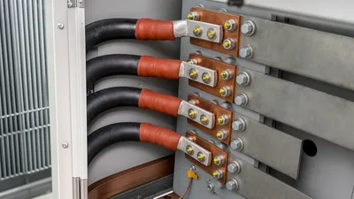
- Bushing turret and inspection cover interfaces: Flanged connections around high-voltage bushings experience mechanical bending moments from connected busbars or cables alongside high cyclical thermal stress. Incorrect initial torque application during installation regularly leads to uneven gasket compression. Readers can review mechanical interface considerations in our transformer bushing engineering guide.
- Radiator and cooling bank headers: Radiator fins operate under continuous vibration induced by core magnetostriction (100 Hz/120 Hz) and forced cooling fans. This dynamic loading causes fatigue cracking at thin-walled radiator element welds, flanged throttle valves, and header connections.
- Tank seam and weld defects: Welded joints on the main transformer tank can harbour latent flaws such as porosity, lack of fusion, or micro-fissures. While transformers pass factory leak testing per IEEE C57.12.00 Table 5, prolonged mechanical vibration and pressure fluctuations from severe load changes can propagate these micro-cracks into through-wall oil seeps.
- Valves and pipe fittings: Drain valves, sampling ports, and gas-detector pipework commonly suffer packing gland degradation or thread galling, especially when copper-alloy fittings interact galvanically with mild steel tank bosses.
Leak Severity Classification and Repair Strategy
Every leak requires categorisation based on fluid loss rate, physical location, and structural risk before selecting a repair methodology.
Engineers classify leaks into three operational tiers:
- Level 1 (Seepage / Weeping): Fluid dampens the surface around a seam or fitting without forming active drops. Free fluid loss is undetectable on the conservator sight glass. These leaks rarely require immediate emergency outages, but moisture can still migrate across the boundary layer via capillary action.
- Level 2 (Active Dripping): Oil coalesces into continuous droplets falling at a rate up to several litres per day. The fluid level in the conservator drops measurably, triggering alarms if left unattended for several weeks.
- Level 3 (Stream / Spray Failure): Continuous stream of insulating fluid resulting from a ruptured radiator fin, cracked pipe, or fully blown gasket seal. This triggers rapid liquid level depletion and poses immediate risks of flashover, gas accumulation, and fire hazards. Detailed containment protocols are explored in our guide to transformer fire protection systems.
Executing a successful transformer leak repair requires matching the intervention to these operational categories. For Level 1 and minor Level 2 leaks where taking an outage threatens regional grid reliability, non-invasive in-situ repairs using engineered structural polymers provide a viable medium-term solution. However, Level 3 failures and leaks beneath the core-and-coil line necessitate controlled de-energisation, containment, and mechanical rebuild.
In-Situ Transformer Leak Repair Using Engineered Sealants
In-situ sealing techniques arrest active leaks without requiring equipment de-energisation or tank fluid evacuation. These methods rely on rapid-curing surface-tolerant epoxies, structural polyurethanes, and mechanical injection clamps designed to adhere directly to oil-wet steel substrates.
For low-pressure seepages on weld seams or tank walls, the standard procedure follows specific sequential stages:
- Surface preparation: Mechanically abrade the substrate 50 mm beyond the leak boundary using non-sparking coarse-grit abrasive discs (ISO 8501-1 St 3 cleanliness standard). The steel profile should exhibit an anchor pattern of approximately 60 to 80 µm. Degrease thoroughly using an industrial solvent that leaves zero residue.
- Localised pressure relief: If oil continues to weep through the surface during preparation, create a negative static pressure inside the tank header (typically -0.05 to -0.10 bar) using a portable vacuum pump attached to the nitrogen blanket or conservator vent. This arrests the outward flow of fluid long enough for the adhesive bond to form.
- Application of rapid-cure sealing paste: Apply a high-reactivity chemical stick or elastomer-infused epoxy putty directly over the crack orifice. This initial compound cures within 2 to 5 minutes, arresting the fluid barrier entirely.
- Structural reinforcement laminate: Overlay the primary plug with a bi-axial woven fiberglass or carbon-composite tape impregnated with an oil-resistant ceramic-filled epoxy paste. Apply this composite layer across a minimum margin of 75 mm beyond the defect, achieving a nominal dry film thickness (DFT) of 2.0 to 3.0 mm.
- Curing: Allow full cross-linking according to the composite manufacturer's thermal cure schedule (typically 2 to 4 hours at 20°C substrate temperature) prior to isolating the vacuum source and restoring positive internal head.
While in-situ composite encapsulation successfully seals weld pores and pinholes, it serves primarily as an operational bridge on flanged joints. Flange expansion cycles will eventually shear adhesive bonds that lack mechanical bolting constraints.
Step-by-Step Procedure: Flanged Gasket Transformer Oil Leak Repair
A permanent transformer oil leak repair on a flanged joint requires dismantling the interface, replacing the elastomer, refacing the steel mating surfaces, and retorquing to engineered compression metrics. The following field procedure applies to inspection manholes, valve necks, and radiator connection flanges.
- Isolation and earthing: De-energise the unit and follow standard Lockout/Tagout (LOTO) procedures. Apply portable working earths to all primary and secondary terminals in accordance with local safety standards before commencing work, coordinating with established transformer maintenance services protocols.
- Oil management: If the component sits below the liquid level, pump oil into clean, dry stainless-steel storage tankers until the liquid level falls at least 150 mm beneath the working plane. Maintain a dry nitrogen gas blanket (0.15 to 0.20 bar) in the headspace to prevent ambient air ingress.
- Flange disassembly: Slacken bolts progressively using a criss-cross pattern to prevent bending stress on the flange neck. Remove old fasteners; corroded bolts must be discarded and replaced with Grade 8.8 hot-dip galvanised or 316 stainless-steel hardware.
- Surface inspection and dressing: Remove old elastomer remnants with brass scrapers. Check flange faces for warpage using a precision straight edge and feeler gauges; maximum permissible planarity deviation is 0.25 mm across the diameter. Machined surfaces should exhibit an arithmetic roughness average (Ra) between 3.2 µm and 6.3 µm to retain the gasket without cutting it.
- Gasket selection and positioning: Use high-grade fluorocarbon (FKM) for high-temperature zones (> 100°C) or hydrogenated nitrile butadiene rubber (HNBR) for standard outdoor installations. Avoid jointed ring gaskets where possible; specify continuous one-piece moulded rings or precision dovetail splices bonded with cyanoacrylate. Never apply liquid RTV silicone sealant alongside elastomer gaskets, as this acts as a lubricant that forces the gasket to extrude out of the joint under compression.
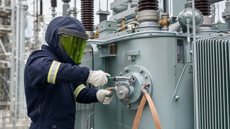
- Controlled bolt torquing: Tighten bolts in four progressive steps using a calibrated torque wrench: finger-tight, 30% torque, 60% torque, and final 100% torque using a diametrically opposed star pattern. The engineering target is to achieve a controlled gasket compression ratio of exactly 25% to 35% of its initial cross-sectional thickness. If the flange features a machined stop or gasket retainer groove, torque the bolts until metal-to-metal contact is achieved between the raised outer flange faces.
Repair Decision Matrix: In-Situ Repair vs Outage Replacement
Selecting between emergency in-situ encapsulation and scheduled component replacement depends on component geometry, mechanical load, and system criticality. The following engineering matrix provides technical boundaries for maintenance planners.
| Leak Origin | Failure Characteristic | Recommended Repair Approach | Outage Required? | Expected Service Life | Applicable Standards |
|---|---|---|---|---|---|
| Tank Body Weld | Pinhole or seam micro-crack (< 3 mm) | Structural epoxy composite wrapping with vacuum pull | No | 3 to 7 years | ASME Section PCC-2 |
| HV Bushing Turret Flange | Elastomer weeping under thermal cycle | Controlled retorque; if failed, gasket replacement | Yes | 15 to 25 years | IEEE C57.19.00 / IEC 60137 |
| Radiator Butterfly Valve | Stem packing gland seepage | Packing nut adjustment or injected gland packing | No | 2 to 5 years | EN 50216-2 |
| Radiator Fin Seam | Fatigue crack from fan vibration | Braze welding or low-viscosity polymer patch | Preferred | 5 to 10 years | DIN 42559 |
| OLTC Compartment Barrier | Internal or external flange leak | Draining of diverter, complete gasket renewal | Yes | 10 to 20 years | IEC 60214-1 |
| Conservator Pipe Flange | Bolted joint weeping via degraded cork | Draining conservator, install FKM/HNBR gasket | Yes | 20+ years | IEC 60076-1 |
Post-Repair Dielectric Testing and Oil Treatment
Following any intrusive mechanical repair or severe fluid leak, restoring the liquid insulation to its baseline dielectric status is mandatory before re-energisation. Atmospheric exposure during maintenance introduces moisture, particulates, and air pockets that severely degrade insulation integrity.
The rehabilitation workflow requires three primary testing and purification phases:
1. Oil filtration and vacuum degassing: Pump the insulating oil through a mobile vacuum processing plant. The fluid must be heated to 60°C ± 5°C, passed through sub-micron particulate filters, and exposed to a deep vacuum (< 1 mbar) inside a vacuum degassing chamber. This removes dissolved water, entrapped nitrogen, and volatile breakdown products. Fluid velocity should not exceed 2.5 m/s across internal surfaces to minimise electrostatic charge generation.
2. Fluid sampling and laboratory analysis: Prior to re-energisation, extract an oil sample per IEC 60475 protocols and execute the following analytical tests:
- Dielectric breakdown voltage: Tested in an oil test cell per IEC 60156 (or ASTM D877/D1816). For equipment operating above 72.5 kV, the breakdown voltage must exceed 60 kV across a standard 2.5 mm hemispherical electrode gap.
- Moisture content: Measured by Karl Fischer coulometric titration (IEC 60814). Water content should measure under 10 ppm for EHV power equipment and under 15 ppm for medium-voltage oil-immersed distribution transformers.
- Dielectric dissipation factor (tan delta): Tested per IEC 60247 at 90°C. Clean oil must yield a dissipation factor < 0.005 (0.5%).
- Dissolved Gas Analysis (DGA): Tested per IEC 60567 to establish a new operational baseline. Verify the absence of combustible gases, particularly acetylene (C2H2) and hydrogen (H2), which indicate internal arcing or partial discharge during the maintenance intervention. Guidance on interpreting baseline dissolved gas figures is detailed in our transformer maintenance engineering guide.
3. Pressure testing: Subject the repaired transformer tank to a static pressure test before commissioning. Apply a positive pressure of 0.35 bar (35 kPa) using dry nitrogen for a duration of 24 hours at ambient temperature. Zero pressure drop over the test cycle verifies absolute hermetic sealing.
Next Steps: Specifying and Sourcing
When recurring oil leaks indicate broader tank fatigue, obsolete design margins, or unresolvable elastomer degradation, complete asset replacement or factory overhaul becomes the most economical long-term strategy. To request a quotation for replacement units or high-performance cooling assemblies, compile your asset data: rated capacity (kVA/MVA), primary/secondary voltages, impedance (%Z), required cooling configuration (ONAN/ONAF), and specific environmental constraints (severe industrial corrosion environments, seismic zone, or ambient extremes).
Our technical team manufactures utility-grade power transformers and distribution units engineered with continuous seam-welded tanks, multi-stage paint finishes, and premium fluorocarbon sealing technology to eliminate leakage risks. Submit your engineering single-line diagrams (SLD) and specifications directly via our transformer quotation page or contact our technical sales engineers for detailed project consultations.
Frequently asked questions
Can you repair a transformer oil leak while the unit is energised?
Yes, non-intrusive external leaks on welds, pipe bodies, and valve casings can be repaired energised using high-strength surface-tolerant polymer composites or external mechanical injection clamps. However, flanged joint dismantling, bushing work, or operations within the minimum approach boundary to live terminals strictly require de-energisation and formal earthing.
What type of gasket material is best for transformer oil leak repair?
Fluorocarbon elastomers (FKM) and hydrogenated nitrile butadiene rubber (HNBR) represent the best materials for modern mineral and synthetic ester oil sealing. They provide superior chemical resistance and maintain elasticity up to 150°C, significantly outperforming legacy cork-nitrile blends.
How much torque should be applied to transformer flange bolts?
Torque must be calculated to achieve 25% to 35% controlled compression of the unconstrained gasket thickness. Exact torque figures depend on bolt diameter, lubrication coefficient, and flange contact area, but typical M12 to M16 hardware on distribution flanges requires between 40 Nm and 85 Nm.
Why is moisture ingress dangerous when a transformer is leaking oil?
As transformer oil expands and contracts during load cycles, outward oil leaks create alternating positive and negative pressure differentials that suck in ambient air and moisture. Water degrades the cellulose paper insulation, reducing the dielectric withstand strength of the windings and accelerating insulation breakdown.
How do you detect the exact source of a hidden transformer oil leak?
Clean the entire suspect area with solvent, spray a dusting of dry chalk, talcum powder, or developer spray across the surface, and pressurise the tank to 0.20 to 0.35 bar. Alternatively, add an oil-soluble fluorescent dye visible under ultraviolet (UV) light, which pinpoints micro-cracks and seam porosity immediately.
Tags: transformer oil leak repair transformer leak repair oil-immersed transformer transformer maintenance substation engineering