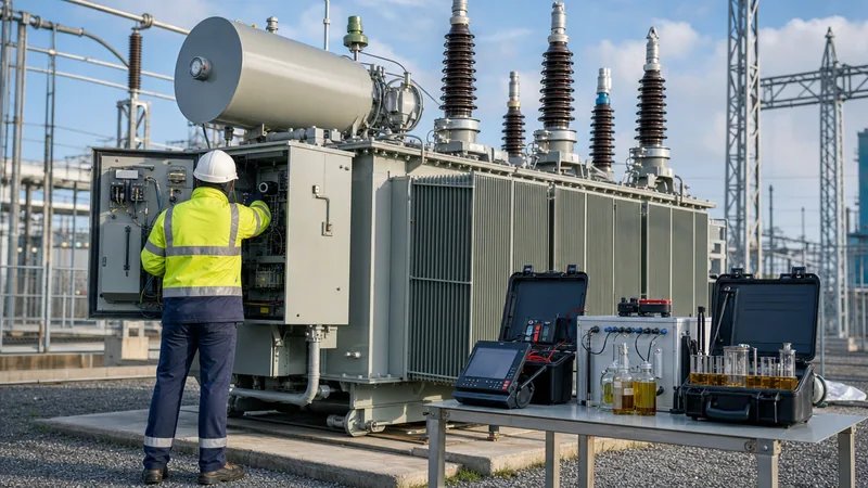
Key takeaways
- Routine transformer maintenance extends asset operating life beyond 35 years by mitigating thermal, dielectric, and mechanical degradation.
- Dielectric breakdown voltage for mineral insulating oil in service must remain above 50 kV (at a 2.5 mm gap) for assets operating at 72.5 kV and above, according to IEC 60422 Table 3.
- Dissolved Gas Analysis (DGA) per IEC 60599 and IEEE C57.104 serves as the primary early-warning diagnostic for incipient thermal faults, partial discharge, and arcing.
- Winding resistance measurements between phases must balance within 2% to rule out shorted turns, contact degradation, or loose internal lead terminations.
- Condition-based maintenance integrating online gas-in-oil and bushing power factor monitoring reduces unplanned outage rates by over 40% compared to purely time-based schedules.
Quick answer: Transformer maintenance is a systematic programme of physical inspections, electrical diagnostic tests, and oil condition monitoring designed to prevent catastrophic asset failure and extend operational life. A compliant maintenance regime adheres to standards such as IEC 60076, IEC 60422, and IEEE C57.152, verifying dielectric integrity, winding geometry, and thermal performance across scheduled operating intervals.
Distribution and power transformers represent critical capital investments in transmission networks, industrial generation plants, and renewable energy substations. Neglecting core and winding condition, insulation ageing, or auxiliary cooling circuits leads directly to unplanned outages, costly environmental remediation, and catastrophic arc-flash events. High-voltage installations operate under continuous thermal and electrical stresses that degrade solid cellulose insulation and liquid dielectrics over time. Implementing structured power transformer servicing protocols preserves capital expenditure and delivers operational predictability across diverse environmental operating conditions.
Power transformer maintenance strategies: Preventive vs predictive
Modern power transformer maintenance strategies divide into time-based preventive maintenance (PM), predictive condition-based maintenance (CBM), and reliability-centred maintenance (RCM). Time-based preventive protocols enforce inspections, mechanical servicing, and fluid testing at fixed calendar intervals regardless of operational severity. Predictive strategies rely on continuous or periodic condition assessments—such as online dissolved gas monitoring and acoustic partial discharge tracking—to target interventions exactly when degradation signatures emerge.
Industry operational data reveals that time-based overhauls alone often introduce human error into previously stable electrical equipment, disturbing internal leads, gaskets, and nitrogen headspaces unnecessarily. Engineering teams increasingly combine continuous online telemetry—as outlined in our transformer monitoring engineering guide—with targeted physical inspections. An effective reliability programme cross-references operational loading profiles, ambient thermal cycles, and historical fault occurrences to establish inspection frequencies, optimising maintenance expenditures while eliminating catastrophic failure vectors across critical substation transformers.
Maintenance of transformer oil: Dielectric testing, limits, and reclamation
Effective maintenance of transformer oil prevents premature dielectric breakdown and minimises hydrolytic degradation of paper insulation. Mineral insulating oil acts as both an electrical dielectric and a heat-transfer fluid, circulating through winding ducts and external radiators. Over time, heat, oxygen exposure, and residual moisture generate polar contaminants, acids, and colloidal sludge. Service personnel must evaluate in-service mineral oil against the compliance thresholds defined in IEC 60422 Table 3 and IEEE C57.106 Table 2.
Key diagnostic parameters for in-service fluid include:
- Dielectric breakdown voltage: Measured using spherical or VDE electrodes across a 2.5 mm gap per IEC 60156. For equipment rated above 72.5 kV, breakdown values must remain above 50 kV; levels dropping below 40 kV necessitate immediate vacuum filtration.
- Water content: Quantified via Karl Fischer coulometric titration (IEC 60814). Acceptable water concentrations must remain below 15 mg/kg (ppm) for transmission-class assets and below 25 mg/kg for distribution units to prevent dielectric quenching.
- Neutralisation value (acidity): Measured in mg KOH/g of oil per IEC 62021-1. Values exceeding 0.15 mg KOH/g accelerate paper depolymerisation, while levels over 0.30 mg KOH/g produce corrosive sludge that blocks cooling passages.
- Dielectric dissipation factor (Tan Delta): Assessed at 90°C per IEC 60247. A dissipation factor exceeding 0.10 indicates high concentrations of soluble polar contaminants or ageing by-products.
- Interfacial tension (IFT): Tested in accordance with ASTM D971. In-service oil exhibiting an IFT below 22 mN/m signals advanced oxidation, requiring fluid regeneration or full replacement.
When physical parameters fall outside safe margins without severe chemical oxidation, technicians implement high-vacuum thermo-physical treatment. For advanced acidification, facilities deploy fuller's earth adsorption systems, details of which are explored in our guide to transformer oil purification.
Diagnostic electrical testing according to IEC 60076 and IEEE C57
Diagnostic electrical testing evaluates internal mechanical geometries, magnetic core integrity, and electrical insulation properties using precision portable test sets. Technicians deploy non-destructive electrical diagnostics during routine outages or following severe through-fault clearances to identify hidden anomalies before re-energisation. The primary testing sequence follows IEEE C57.152 and IEC 60076-1 guidelines, isolating the winding and core from the utility network.
The standard testing workflow includes:
- Insulation resistance and polarisation index (PI): DC voltages of 2.5 kV or 5 kV are applied between HV windings, LV windings, and the grounded tank for 10 minutes. The ratio of 10-minute to 1-minute insulation resistance provides the PI; values below 1.5 indicate surface contamination or absorbed moisture.
- Winding resistance measurements: High-precision Kelvin bridge or digital low-resistance ohmmeters (DLRO) inject regulated DC current through each phase tap position to detect broken conductor strands, dry joints, or tap changer contact wear. Phase balance deviations must not exceed 2%.
- Voltage turns ratio (VTR): Tests verify actual turns ratios across every tap changer position against nameplate specification to within ±0.5% tolerance (IEC 60076-1 clause 9.3). Phase angle displacement verifies vector group integrity (such as Dyn11 or YNd1).
- Insulation power factor / tan delta: 10 kV AC testing characterises the dielectric losses of bulk insulation and condenser bushings, directly flagging carbon tracks, water infiltration, and thermal breakdown.
- Frequency Response Analysis (SFRA): Low-voltage high-frequency sweep signals (typically 20 Hz to 2 MHz) detect millimetre-scale winding displacements, axial buckling, and core hoop deformations resulting from electromagnetic stresses during external short-circuits (IEC 60076-18).
Worked calculation: Winding resistance temperature correction and balance
Accurate field validation of winding resistance requires correcting raw measurements taken at ambient temperature back to a standardised reference temperature, typically 75°C for standard liquid-filled units (IEC 60076-1 clause 10.2). Without accurate thermal compensation, technicians cannot validly compare baseline factory acceptance data against field measurements, risking false fault indications or undetected coil damage.
The temperature correction formula for copper conductors is:
R_ref = R_meas × (T_k + T_ref) / (T_k + T_meas)
Where:
- R_ref = corrected winding resistance at reference temperature (Ω)
- R_meas = measured winding resistance on site (Ω)
- T_k = material constant (234.5°C for annealed copper, 225.0°C for aluminium)
- T_ref = reference temperature (75.0°C)
- T_meas = winding oil temperature during measurement (°C)
Consider a 33 kV / 11 kV 20 MVA oil-immersed transformer with copper windings. High-voltage winding resistance measurements taken on Phase A-B, B-C, and C-A at an oil temperature of 38.0°C yield the following field readings:
- R_meas(A-B) = 0.2415 Ω
- R_meas(B-C) = 0.2422 Ω
- R_meas(C-A) = 0.2468 Ω
First, correct Phase A-B to the 75°C reference base:
R_75(A-B) = 0.2415 × (234.5 + 75.0) / (234.5 + 38.0) = 0.2415 × (309.5 / 272.5) = 0.2415 × 1.13578 = 0.2743 Ω
Applying the identical thermal factor (1.13578) to the remaining phases yields:
- R_75(B-C) = 0.2422 × 1.13578 = 0.2751 Ω
- R_75(C-A) = 0.2468 × 1.13578 = 0.2803 Ω
Next, evaluate the phase balance percentage deviation per IEEE C57.152 recommendations using the average corrected value:
R_avg = (0.2743 + 0.2751 + 0.2803) / 3 = 0.2766 Ω
Maximum deviation occurs on Phase C-A:
Deviation (%) = (|0.2803 - 0.2766| / 0.2766) × 100 = (0.0037 / 0.2766) × 100 = 1.34%
Because the deviation (1.34%) sits below the allowable 2.0% threshold, the winding passes operational screening. For an exhaustive procedure on interpreting winding continuity and test equipment, review our guide to the winding resistance test of transformer.
Transformer maintenance schedule: Routine inspection intervals
A structured transformer maintenance schedule defines clear tasks, inspection frequencies, and target thresholds across the operating life of an asset. Adhering to these intervals prevents minor issues—such as clogged breathers or weeping valves—from compounding into severe dielectric or thermal failures.
| Inspection Interval | Maintenance Task | Reference Standard | Pass Criteria / Action Threshold |
|---|---|---|---|
| Daily / Weekly | Check top oil and winding temperature indicators (OTI/WTI) | IEC 60076-2 | Operating within design loading limit; margin > 15°C below trip |
| Monthly | Inspect dehydrating breather silica gel condition | IEC 60076-1 | Less than two-thirds pink/blue discoloration; oil bath clean |
| Monthly | Inspect nitrogen blanket pressure (sealed units) | IEEE C57.12.00 | Positive pressure sustained between 0.015 MPa and 0.035 MPa |
| Quarterly | Visual inspection of tank, valves, and radiators for oil leaks | Local environmental regs | Zero active drops; dry flange surfaces |
| Annually | Oil sampling for DGA and physicochemical analysis | IEC 60422 / IEC 60599 | Moisture < 20 ppm; breakdown voltage > 50 kV; gases normal |
| Annually | Functional check of Buchholz relay and pressure relief valve | IEC 60076-1 | Contacts operate smoothly; micro-switch continuity confirmed |
| Every 3 to 5 Years | Full diagnostic electrical testing (TTR, Winding Res., SFRA) | IEEE C57.152 | Ratio < ±0.5%; winding dev. < 2%; SFRA profile matches base |
| Every 5 Years | On-Load Tap Changer (OLTC) internal mechanism inspection | Manufacturer manuals | Measure contact wear; filter diverter switch compartment oil |
Mechanical inspection, tank preservation, and bushing maintenance
Mechanical inspection focuses on the physical integrity of structural components, fluid containment boundaries, and external insulation interfaces. Structural deterioration caused by rust, vibrational fatigue, or ambient ultraviolet radiation compromises hermetic seals, allowing water and airborne contaminants to enter the main tank cavity.
Critical physical areas demanding rigorous servicing include:
- High-voltage bushings: Bushings operate under severe dielectric field stress. Technicians must clean porcelain or composite sheds regularly using approved solvents to eliminate salt crusts and industrial dust that cause surface tracking. Condenser-type bushings require annual power factor and capacitance checks via the test tap; a capacitance change of more than 5% relative to the nameplate denotes internal dielectric layer puncture, necessitating immediate bushing replacement as detailed in our transformer bushing engineering guide.
- Gasketed joints and valves: Nitrile or fluoroelastomer gaskets harden over thermal cycles, precipitating active leaks. Torque tank perimeter bolts crosswise to specified mechanical values; overtightening crushes the elastomer and causes flange seepage.
- Buchholz and safety relays: Collect gas accumulations from the upper chamber of the Buchholz relay and perform flame tests or chromatographic analysis to confirm whether trapped volume represents harmless compressed air or combustible fault gas. Test trip and alarm circuits by manually exercising relay float switches.
- Pressure relief device (PRD): Inspect operating visual flags and test auxiliary trip switches. Ensure the safety discharge path routes safely away from walkways and secondary switchgear.
Thermal and cooling system servicing: Forced-air and dry-type units
Maintaining transformer cooling systems ensures internal operating temperatures remain below class-rated insulation limits (such as 105°C for mineral oil Class A systems or 155°C/180°C for Class F/H dry-type assets). Radiator banks, circulating pumps, and forced-air fans directly control the thermal gradient between hot-spot winding conductors and ambient air.
For liquid-immersed units fitted with forced-air cooling, technicians clean radiator banks annually using compressed air or low-pressure hot-water washdowns to dislodge leaf litter and airborne dust. Check fan motor bearings for vibrational play, measure running motor currents against nameplate ratings, and confirm automated stage start/stop setpoints on the control cubicle. Radiator butterfly valves must remain fully pinned open during normal operation to prevent localised oil stagnation.
In contrast, dry-type transformers rely entirely on unhindered convection and auxiliary cross-flow blowers. Maintenance involves removing enclosure louvre filters, vacuuming dust deposits from resin casting ducts, and torquing busbar bolted connections to eliminate hot spots. Engineers can contrast liquid and air-insulated service profiles across our guide to dry type transformers.
Diagnostic interpretation: DGA, moisture calculation, and paper ageing
Diagnostic interpretation of Dissolved Gas Analysis (DGA) data identifies incipient electrical and thermal faults within liquid-insulated equipment long before protective relays trigger an outage. When insulation oil and cellulosic paper endure thermal or electrical stress, chemical bonds fracture, yielding measurable concentrations of fault gases: hydrogen (H2), methane (CH4), ethane (C2H6), ethylene (C2H4), acetylene (C2H2), carbon monoxide (CO), and carbon dioxide (CO2).
Engineers evaluate gas generations using established analytical standards:
- Duval Triangle 1 (IEC 60599): Uses relative percentages of CH4, C2H4, and C2H2 plotted on a triangular coordinate system to categorise faults into thermal faults (low, medium, high temperature: TK1, TK2, TK3), partial discharge (PD), and low- or high-energy discharges (D1, D2). The appearance of even trace amounts of acetylene (C2H2 > 1 to 2 ppm) signifies high-energy arcing between turns or to ground.
- Carbon oxide ratios: The ratio of CO2 to CO provides an index of cellulosic degradation. Healthy paper insulation yields a carbon dioxide to carbon monoxide ratio between 3 and 10. A ratio dropping below 3 combined with elevated absolute levels indicates accelerated paper carbonisation, while ratios exceeding 20 denote low-temperature paper heating.
- Degree of Polymerisation (DP): New kraft paper possesses a DP value around 1,000 to 1,200. Continued operation under high temperatures and moisture breaks the long-chain cellulose polymers down. When the DP drops to 200–250, the mechanical tensile strength of the turn-to-turn paper insulation is exhausted; under this condition, the transformer reaches the end of its reliable operational life, because an external system through-fault can mechanically shatter the brittle paper and precipitate short-circuits.
For field personnel executing overall testing, see our practical procedure in how to test a transformer.
Next steps: specifying and sourcing
When existing power equipment shows advanced cellulosic breakdown, chronic gas evolution, or unresolvable dielectric deterioration, asset replacement becomes the safest engineering strategy. Sourcing dependable, compliant medium- and high-voltage power units requires specifying key operational criteria: nominal rated capacity (kVA/MVA), primary and secondary voltages, BIL ratings, vector group, short-circuit impedance limits, and tailored auxiliary cooling packages.
Our engineering team designs and manufactures utility-grade power transformers, distribution units, and skid-mounted transformer substations strictly compliant with IEC 60076 and IEEE C57 series standards. To discuss specific site requirements, submit technical single-line diagrams, or request an engineering tender proposal, visit our dedicated transformer quotation page or connect directly with our application engineers via our contact page.
Frequently asked questions
What is the most critical test in transformer maintenance?
Dissolved Gas Analysis (DGA) is widely regarded as the most critical diagnostic test in transformer maintenance. It detects thermal faults, arcing, and partial discharge in their earliest stages without requiring equipment de-energisation.
How often should transformer maintenance be conducted?
Basic visual checks and temperature logging should be conducted weekly or monthly, with oil sampling and DGA carried out annually. Comprehensive off-line electrical diagnostic testing typically occurs every three to five years, or following a major system through-fault.
What causes transformer oil to degrade over time?
Transformer oil degrades primarily through oxidation driven by operational heat and atmospheric oxygen exposure, accelerated by moisture and metallic catalysis from copper and iron. This oxidation chain creates acids, sludge, and polar molecules that impair dielectric strength and thermal heat transfer.
What is the acceptable dielectric breakdown voltage for transformer oil?
In-service mineral oil for transformers operating above 72.5 kV must maintain a breakdown voltage of at least 50 kV when tested across a 2.5 mm gap per IEC 60156. For lower-voltage distribution transformers below 72.5 kV, the minimum acceptable threshold is generally 40 kV.
What is the difference between dry-type and oil-filled transformer maintenance?
Oil-immersed transformer maintenance focuses heavily on fluid testing, oil filtration, gasket sealing, and DGA interpretation. Dry-type maintenance eliminates fluid testing and instead prioritises physical cleanliness, vacuuming dust deposits from ventilation ducts, inspecting epoxy castings for partial discharge tracking, and torquing bolted electrical connections.
Tags: transformer maintenance electrical transformer maintenance maintenance of transformer oil power transformer maintenance


