Key takeaways
- Selecting thinner transformer core lamination material, such as 0.23 mm over 0.30 mm, reduces classical eddy current losses proportionally to the square of the sheet thickness.
- Grain-oriented electrical steel (CRGO) aligned along the rolling direction offers relative magnetic permeability exceeding 10,000 and reduces hysteresis loss compared to non-oriented steels.
- Laser-scribed and domain-refined CRGO grades achieve specific core losses below 0.80 W/kg at 1.7 T and 50 Hz, delivering substantial lifetime energy savings in medium and high-voltage units.
- ASTM A976 Class C-5 inorganic insulation coatings provide the necessary inter-laminar electrical resistance while withstanding stress-relief annealing temperatures up to 820 °C.
- Step-lap mitred joints stacked in 5-step or 7-step configurations minimise localized flux crowding and air gaps at the corner joints, lowering both no-load current and acoustic noise.
Quick answer: The standard transformer core lamination material is cold-rolled grain-oriented (CRGO) silicon electrical steel, supplied in thicknesses from 0.20 mm to 0.30 mm. Selecting modern domain-refined CRGO sheets coated with inorganic insulation suppresses eddy currents, slashes no-load core losses to under 0.85 W/kg at 1.7 T, and optimises lifetime operational efficiency.
Designing efficient magnetic circuits requires balancing material permeability, saturation flux density, and thermal dissipation. In high-voltage equipment detailed in our transmission transformer engineering guide, core excitation losses continue non-stop for decades once energised. Specifying the optimal transformer core lamination material directly controls building factors, limits audible hum, and curtails lifecycle utility costs across industrial and utility distribution networks.
Why Transformer Core Lamination is Essential for Loss Reduction
Magnetic cores are laminated rather than solid to break bulk conductive loops that otherwise induce massive eddy currents and generate unacceptable internal heating. In a laminated iron core transformer, magnetic flux passes through thousands of individual, electrically insulated sheets stacked parallel to the flux lines, restricting eddy current circulation to the narrow cross-section of each single sheet.
Core losses consist primarily of hysteresis losses and classical eddy current losses, supplemented by anomalous excess losses. Classical eddy current loss per unit mass ($P_e$, expressed in W/kg) is governed by the following physical relationship:
$$P_e = \frac{\pi^2 \cdot f^2 \cdot B_m^2 \cdot t^2}{6 \cdot \rho \cdot D}$$
Where $f$ represents the operating frequency in Hertz, $B_m$ is the peak magnetic flux density in Tesla, $t$ is the individual lamination thickness in metres, $\rho$ denotes the electrical resistivity of the steel in $\Omega\cdot\text{m}$, and $D$ is the material mass density in $\text{kg/m}^3$. Because the lamination thickness $t$ is squared in the numerator, cutting sheet thickness from 0.35 mm to 0.23 mm reduces classical eddy current dissipation by more than 56%. Silicon additions of 3.0% to 3.4% by weight further increase the base electrical resistivity $\rho$ from approximately $10 \times 10^{-8}\;\Omega\cdot\text{m}$ (pure iron) to roughly $45\text{--}50 \times 10^{-8}\;\Omega\cdot\text{m}$, directly suppressing circulating micro-currents within the magnetic framework outlined in our guide to transformers internal components.
Types and Grades of Transformer Core Lamination Material
Modern magnetic cores utilise cold-rolled grain-oriented silicon steels classified under international standards such as IEC 60404-8-7 and EN 10107. Commercial transformer core lamination material grades fall into three primary metallurgic categories:
- Conventional Grain-Oriented (CGO) Steel: Processed via single or double cold-reduction stages to establish the Goss texture ((110)[001] crystal alignment). CGO materials (e.g., M4, M5, or IEC grades 30M130, 27M120) offer reliable performance at operating flux densities up to 1.6 T, serving standard distribution applications effectively.
- High-Permeability Grain-Oriented (Hi-B) Steel: Synthesised using aluminium nitride inhibitors to narrow crystal misorientation to within 3° of the rolling axis. Hi-B grades (e.g., 27ZH100, 23ZH090) exhibit high relative permeability ($>10,000$) and lower magnetostriction, enabling quiet operation and lower excitation currents at elevated working densities between 1.65 T and 1.75 T.
- Laser-Scribed / Domain-Refined Steel: High-permeability steel treated with non-contact laser scribing or plasma etching across the rolling axis. The localized surface thermal stress divides broad magnetic domain walls into narrow domains, decreasing anomalous dynamic losses by 10% to 20%. These sheets cannot undergo stress-relief annealing above 500 °C without losing the scribing effect, making them ideal for stacked, non-annealed mitred assemblies.
- Amorphous Metal Alloys: Non-crystalline iron-boron-silicon ribbon alloys ($~0.025\text{ mm}$ thick) with exceptionally low coercivity. While amorphous cores exhibit no-load losses roughly 70% below conventional CRGO, their lower saturation point ($~1.56\text{ T}$ vs. $2.03\text{ T}$ for CRGO), lower stacking density, and brittle handling characteristics generally confine them to specialised low-loss padmount and pole-mounted designs.
For large power units and high-capacity units built in transformer core engineering programs, Hi-B and domain-refined grades remain the global industry benchmark for volumetric power density and operational reliability.
Thickness, Stacking Factor, and Specific Loss Comparison
Selecting the optimal sheet thickness requires evaluating the trade-off between reduced specific losses and lower structural stacking factors. Thinner sheets introduce more insulation interfaces per unit height, reducing the net active iron volume inside the winding window.
| Standard Grade (IEC 60404-8-7) | Nominal Thickness (mm) | Specific Loss at 1.5 T, 50 Hz (W/kg) | Specific Loss at 1.7 T, 50 Hz (W/kg) | Stacking Factor ($k_s$) | Target Transformer Type |
|---|---|---|---|---|---|
| 30M130 (Conventional) | 0.30 | 0.92 | 1.30 | 0.965 | Standard distribution (< 500 kVA) |
| 27M120 (Conventional) | 0.27 | 0.85 | 1.20 | 0.960 | Medium power distribution |
| 27ZH100 (Hi-B) | 0.27 | 0.74 | 1.00 | 0.960 | Medium industrial & substation units |
| 23ZH090 (Hi-B) | 0.23 | 0.68 | 0.90 | 0.955 | High-efficiency MV/HV transformers |
| 23ZDKH085 (Domain-Refined) | 0.23 | 0.60 | 0.82 | 0.955 | Large generation & transmission GSUs |
| 20ZDKH075 (Domain-Refined) | 0.20 | 0.54 | 0.74 | 0.945 | Ultra-low-loss Tier 2 / Tier 3 units |
As indicated in the engineering data above, moving from a standard 0.30 mm gauge down to a 0.23 mm domain-refined grade drops total specific core losses at 1.7 T by nearly 37%. However, the stacking factor ($k_s$) declines from 0.965 to 0.955, requiring a slight compensation in core cross-sectional area to preserve equal net iron mass without over-exciting the steel.
Insulation Coatings and Surface Treatments (C-3 to C-5)
Surface coatings on transformer core lamination material provide crucial inter-laminar electrical insulation to stop eddy currents crossing between adjacent plates under clamping pressure. Electrical steel insulation classes are standardized in ASTM A976 and IEC 60404-1-1, defining temperature endurance, dielectric capability, and weldability.
The standard treatment for power transformer core lamination is an inorganic phosphate coating (ASTM A976 Class C-5 over a Class C-2 base glass film, frequently termed Carlite insulation). During secondary recrystallisation in manufacturing, a primary magnesium silicate film (C-2) forms on the steel surface. The factory then applies an inorganic liquid phosphate coat and cures it under tension. This double-layer system exhibits the following key properties:
- Surface insulation resistance exceeding $30\;\Omega\cdot\text{cm}^2$ per strip at 2.0 MPa test pressure (IEC 60404-2 Franklin tester).
- Thermal endurance capable of withstanding industrial nitrogen stress-relief annealing cycles at 800 °C to 820 °C without flaking or dielectric degradation.
- Permanent isotropic surface tension that lowers micro-eddy drag and suppresses magnetostrictive vibration hum.
- Complete chemical neutrality and insolubility in synthetic esters, natural esters, and mineral insulating oils compliant with IEC 60296.
For dry-type transformers, Class C-4 or C-5 inorganic coatings ensure absolute flame retardance without emitting toxic vapours under elevated winding and core operating temperatures up to 180 °C.
Step-Lap Mitred Stacking and Core Assembly Procedures
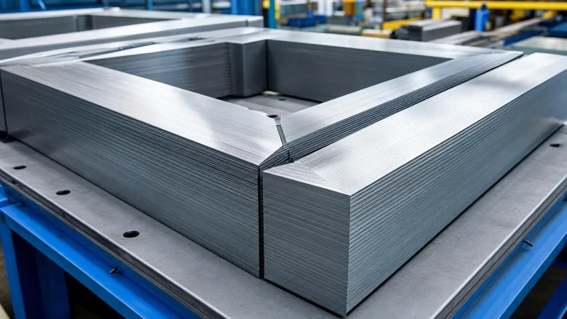
Stacking geometry dictates whether the low-loss potential of premium transformer core lamination is successfully realised or degraded by mechanical assembly stresses. Mitred step-lap stacking is the modern standard for oil-immersed and dry-type magnetic limbs.
- Slitting and Precision Shearing: Mother coils of CRGO electrical steel are slit into strip ribbons matching core packet limb widths using carbide or ceramic circular knives, maintaining edge burrs below 0.015 mm.
- Step-Lap Mitred Cutting: Computerised cut-to-length CNC lines cut 45° corner joints and 90°/45° center-leg chevron joints, introducing incremental lateral offsets (typically 3.0 mm to 5.0 mm per step across 5 to 7 steps) along adjacent lamination ends.
- Deburring and Demagnetisation: Sheared laminations pass through high-frequency inline de-magnetisers and automated deburring rollers to eliminate residual localized shear strain and magnetic memory.
- Limb and Yoke Stacking: Technicians assemble laminations horizontally over precision jig pins in alternating 5-step or 7-step sequence groups (e.g., book-stack or step-lap layups), bridging joints smoothly to eliminate straight cross-core air gaps.
- Core Clamping and Banding: The assembled packets are consolidated using resin-impregnated fibreglass banding tape or non-magnetic stainless steel tie plates tightened to controlled torque (typically 0.35 to 0.50 MPa contact pressure across the core face), preventing sheet fluttering and excessive joint gap creation.
- Protective Edge Sealing: The exposed outer edges of the assembled iron limbs receive an epoxy or polyurea resin coating to seal cut edges against atmospheric moisture, oxidation, and transit vibration.
Implementing multi-step lap joints reduces joint transfer losses by up to 15% and drops acoustic sound pressure levels by 3 to 6 dB(A) compared to traditional single-lap mitred corners.
Worked Calculation: Eddy Current Loss Reduction by Sheet Thickness
A direct mathematical comparison illustrates the physical loss differences achieved by substituting thinner transformer core lamination material in a 2,500 kVA, 50 Hz substation transformer. The magnetic design parameters are defined as follows:
- Active net core mass ($M$): $3,800\text{ kg}$
- Operating peak magnetic flux density ($B_m$): $1.70\text{ T}$
- Core operating frequency ($f$): $50\text{ Hz}$
- Core steel mass density ($D$): $7,650\text{ kg/m}^3$
- Electrical resistivity of 3.2% Si steel ($\rho$): $48 \times 10^{-8}\;\Omega\cdot\text{m}$
Using the classical eddy current equation $P_e = \frac{\pi^2 \cdot f^2 \cdot B_m^2 \cdot t^2}{6 \cdot \rho \cdot D}$:
The constant factor $K = \frac{\pi^2 \cdot f^2 \cdot B_m^2}{6 \cdot \rho \cdot D}$ is calculated first:
$$\pi^2 \cdot (50)^2 \cdot (1.70)^2 = 9.8696 \times 2,500 \times 2.89 = 71,308$$
$$6 \cdot \rho \cdot D = 6 \times (48 \times 10^{-8}) \times 7,650 = 0.022032$$
$$K = \frac{71,308}{0.022032} = 3,236,565\;\text{W/}(\text{kg}\cdot\text{m}^2)$$
Now compute the specific classical eddy current loss ($p_e$) for 0.30 mm versus 0.23 mm laminations:
For $t_1 = 0.30\text{ mm} = 3.0 \times 10^{-4}\text{ m}$:
$$p_{e(0.30)} = 3,236,565 \times (3.0 \times 10^{-4})^2 = 3,236,565 \times 9.0 \times 10^{-8} = 0.2913\;\text{W/kg}$$
Total classical eddy loss across the $3,800\text{ kg}$ core:
$$P_{e(0.30)} = 0.2913\text{ W/kg} \times 3,800\text{ kg} = 1,106.9\text{ W}$$
For $t_2 = 0.23\text{ mm} = 2.3 \times 10^{-4}\text{ m}$:
$$p_{e(0.23)} = 3,236,565 \times (2.3 \times 10^{-4})^2 = 3,236,565 \times 5.29 \times 10^{-8} = 0.1712\;\text{W/kg}$$
Total classical eddy loss across the $3,800\text{ kg}$ core:
$$P_{e(0.23)} = 0.1712\text{ W/kg} \times 3,800\text{ kg} = 650.6\text{ W}$$
Direct net power saving in classical eddy dissipation:
$$\Delta P_e = 1,106.9\text{ W} - 650.6\text{ W} = 456.3\text{ W}$$
Operating 8,760 hours per year continuously over a 30-year design life, this single parameter adjustment conserves $119,915\text{ kWh}$ of electrical energy. This reduction excludes concurrent reductions in anomalous dynamic eddy losses, confirming the substantial lifecycle financial and environmental value of specifying high-performance thin-gauge laminations during design acceptance as detailed in our power transformer testing guide.
Factory Quality Control and Core Inspection Checklist
Rigorous factory acceptance testing prevents damaged or inferior electrical steel from entering production assemblies. Mechanical shearing, punching, and improper stacking introduce edge stresses that dramatically degrade relative permeability and increase core losses.
Procurement engineers and quality inspectors should enforce the following quantitative acceptance benchmarks during factory audits:
- Burr Height Verification: Measure edge burrs using optical micrometers; maximum allowable height must not exceed $0.020\text{ mm}$ ($0.015\text{ mm}$ preferred on thin $\le 0.23\text{ mm}$ sheet) to avoid puncturing the inter-laminar insulation film.
- Surface Insulation Resistance: Verify coating integrity according to IEC 60404-2 Franklin test methods. A minimum individual test value of $10\;\Omega\cdot\text{cm}^2$ and a batch mean above $30\;\Omega\cdot\text{cm}^2$ ensure adequate inter-sheet isolation.
- Specific Iron Loss Measurement: Conduct Epstein frame tests (IEC 60404-2) or single-sheet sensor measurements (IEC 60404-3) on incoming coil slit samples at 1.5 T and 1.7 T (50/60 Hz) prior to limb cutting.
- Building Factor ($BF$) Auditing: The ratio of final measured core no-load loss to the theoretical material loss (Epstein base) must fall between $1.08$ and $1.18$ for step-lap mitred power cores. A $BF > 1.25$ indicates poor clamping pressure uniformity, excessive edge burrs, or mechanical over-stressing during stacking.
- Clamping Torque and Pressure Limits: Core limb bolts or outer resin bandage tension must maintain uniform compressive pressure between $0.35\text{ MPa}$ and $0.50\text{ MPa}$. Insufficient pressure elevates vibration noise; excessive pressure induces mechanical compressive stress that raises hysteresis losses.
Next steps: specifying and sourcing
When specifying magnetic cores for upcoming capital infrastructure projects, detail the nominal sheet thickness, minimum steel grade, guaranteed maximum no-load watts per kilogram, and joint configuration in your technical schedule. Our engineering team assists project consultants, EPCs, and utility engineers in balancing core dimensions, total capital expenditure, and 30-year loss evaluations. Explore our heavy-duty power transformer solutions, high-efficiency oil-immersed transformer range, and commercial dry-type transformer systems. Submit your technical project specifications through our transformer quotation portal to receive fully optimised magnetic design calculations and commercial bids.
Frequently asked questions
What is the best transformer core lamination material?
Cold-rolled grain-oriented (CRGO) silicon steel is the industry benchmark for power and distribution transformers. For the lowest no-load losses, thin-gauge (0.20 mm to 0.23 mm) laser-scribed or domain-refined Hi-B electrical steels deliver the highest performance, holding losses under 0.85 W/kg at 1.7 Tesla.
Why are transformer cores made of laminations instead of solid iron?
Solid iron cores act as short-circuited single-turn conductors in the presence of alternating magnetic flux, inducing massive circulating eddy currents that cause rapid thermal overheating and extreme power loss. Laminating the core divides the cross-section into thin, electrically isolated slices, keeping eddy current losses down to negligible levels.
How does lamination thickness affect transformer core loss?
Classical eddy current loss is directly proportional to the square of lamination thickness. Thinning the steel sheets from 0.30 mm to 0.23 mm cuts classical eddy current losses by approximately 41%, significantly reducing operational heat and lowering no-load losses over the equipment's lifespan.
Can transformer laminations be re-annealed after cutting?
Conventional and standard Hi-B CRGO laminations can undergo continuous stress-relief annealing at 800 °C to 820 °C in an inert nitrogen atmosphere to restore magnetic properties degraded by mechanical shearing. However, laser-scribed (domain-refined) grades must not be annealed above 500 °C, as excessive heat removes the engineered surface domain walls.
What coating is used to insulate transformer core laminations?
ASTM A976 Class C-5 inorganic phosphate coatings (commonly known as Carlite) are applied over the base magnesium silicate glass layer. This non-flammable coating withstands stress-relief annealing temperatures up to 820 °C, resists transformer mineral oil and ester fluids, and provides surface insulation resistance exceeding 30 ohm-cm².
What is the difference between CRGO and amorphous core material?
CRGO is crystalline silicon steel (0.20 mm to 0.30 mm thick) with high saturation induction (roughly 2.03 T) and robust mechanical rigidity. Amorphous core material is a non-crystalline metallic alloy foil (0.025 mm thick) with much lower no-load loss but a lower saturation flux density (1.56 T), higher manufacturing fragility, and larger total core volume.
Tags: transformer core lamination material laminated iron core transformer transformer core lamination power transformers electrical steel


