Key takeaways
- A toroidal core is a closed ring with no air gap, so leakage flux and external magnetic field are much lower than in a stacked EI core.
- Using N = V / (4.44 × f × A × B), a 230 V, 50 Hz toroid at 1.5 T on 14.25 cm² needs about 485 turns.
- Gapless toroids have high remanence, so energizing inrush can reach many times rated current; soft-start circuits or slow-blow fuses are standard practice.
- Ferrite toroid cores (MnZn or NiZn) serve kilohertz-to-megahertz circuits, while silicon-steel toroids serve 50 and 60 Hz power.
- Above roughly 5–10 kVA, stacked-core dry-type or oil-immersed transformers become more economical and easier to cool than toroids.
Quick answer: A toroidal transformer is a transformer wound on a ring-shaped (toroidal) core, usually a continuous strip of grain-oriented silicon steel. The closed, gapless magnetic path gives low stray magnetic field, low hum, compact size and low no-load loss compared with EI-laminated designs, but it draws high inrush current and is practical mainly from a few VA up to a few kVA.
Open a high-end audio amplifier, a medical monitor or a lighting controller and there is a good chance you will find a doughnut-shaped transformer wrapped in tape. Toroids earned that place because they are quiet, compact and leak very little magnetic field into nearby circuits.
This guide is for electronics designers, panel builders and engineers specifying small power supplies. It explains how a toroidal transformer differs from EI and C-core designs, which core materials suit which frequency, how to calculate turns and inductance, why toroids are known for inrush problems, and when a project should move up to a conventional dry-type distribution transformer.
What Is a Toroidal Transformer?
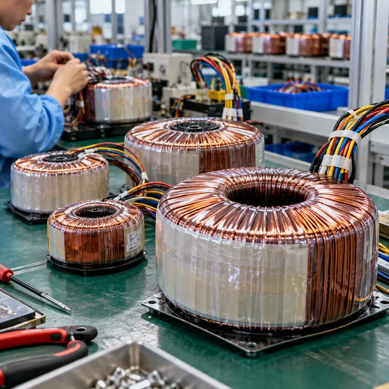
A toroidal transformer is a transformer whose primary and secondary windings are wound around a ring-shaped core. The core is usually made by winding a long, narrow strip of grain-oriented silicon steel into a tight coil, like a roll of tape, then annealing it to restore the magnetic properties lost during winding. The copper windings are then threaded through the centre hole and distributed evenly around the full circumference.
This construction has three consequences:
- The flux follows the grain. In a strip-wound ring the magnetic path always runs along the rolling direction of the steel, where grain-oriented steel has its lowest loss and highest permeability. In an EI stack, part of the path crosses the grain at the corners.
- There is no air gap. EI laminations have butt joints where E and I pieces meet; a wound toroid has none. Magnetising current is very low and stray field is small.
- Windings cover the core uniformly. Leakage flux is mostly contained, so a toroid can sit close to sensitive circuits without inducing hum.
A toroid transformer is therefore lighter and smaller than an EI transformer of equal rating, often by a substantial margin, and mechanical hum is low because there are no loose laminations to vibrate. The trade-offs are winding cost (each turn must pass through the hole, which needs special shuttle winding machines), limited practical size and a high energizing inrush. For the basics of core construction in larger units, see our transformer core engineering guide.
Toroidal Core vs EI Core vs C-Core
The toroidal core is one of three common shapes for small power transformers. Each balances cost, performance and manufacturability differently.
| Property | Toroidal core | EI laminated core | C-core (cut wound) |
|---|---|---|---|
| Magnetic path | Closed ring, no gap | Stacked, butt joints | Wound and cut, two small gaps |
| Grain orientation | Always along path | Crosses grain at corners | Along path |
| Stray magnetic field | Very low | Higher | Low to moderate |
| Size and weight | Smallest | Largest | Intermediate |
| Audible hum | Very low | Can be noticeable | Low |
| Energizing inrush | High (gapless, high remanence) | Moderate | Lower (gaps reduce remanence) |
| Winding cost | Higher; toroidal winding machine | Lowest; bobbin winding | Low; bobbin winding |
| Practical range | About 10 VA to a few kVA | VA to tens of kVA | VA to tens of kVA |
Core steel choice matters as much as shape. Thinner laminations and higher grades of grain-oriented steel reduce eddy current and hysteresis loss; amorphous and nanocrystalline ribbons, also wound into toroids, reduce no-load loss further. Our guide to transformer core lamination materials compares these grades. For mounting, toroids are fixed with a single central bolt and rubber pads, or potted in resin with a central metal insert. The central bolt must never form a closed conductive loop through the chassis, or it becomes a shorted turn that overheats and can blow the supply fuse.
Ferrite Toroid Cores and Toroidal Inductors
Searches for toroidal inductors and transformers often mix two worlds: 50/60 Hz power transformers on steel cores, and high-frequency magnetics on ferrite or powder cores. The ring shape is the same; the material is chosen for frequency.
| Core material | Typical frequency | Saturation flux (approx.) | Typical use |
|---|---|---|---|
| Grain-oriented silicon steel | 50–400 Hz | 1.5–1.9 T | Mains power transformers |
| Amorphous / nanocrystalline ribbon | 50 Hz to about 100 kHz | 1.2–1.6 T | Low-loss transformers, current sensors, chokes |
| MnZn ferrite | About 10 kHz to 1 MHz | About 0.4–0.5 T | SMPS transformers, common-mode chokes |
| NiZn ferrite | About 1 MHz to hundreds of MHz | About 0.3–0.4 T | EMI suppression, RF transformers, baluns |
| Iron powder / alloy powder | kHz to MHz | About 0.7–1.5 T | Energy storage inductors with distributed gap |
A ferrite toroid core (or toroidal ferrite core) has high permeability and low eddy loss at high frequency, but low saturation flux, so designers work well below 0.5 T. A toroid core made from pressed powder has a distributed air gap that lets it store energy without saturating, which is what an output inductor in a DC-DC converter needs. The difference between storing energy and transferring it is explained in our inductor vs transformer article.
Core suppliers publish an inductance factor AL in nH per turn squared, so inductance is simply L = AL × N². A ferrite toroid with AL = 2,000 nH/N² wound with 10 turns gives 2,000 × 100 = 200,000 nH = 200 µH. The equivalent physics form is L = μ0 × μr × N² × Ae / le, where Ae is core cross-section and le the mean magnetic path length.
How to Calculate Turns for a Toroidal Transformer
Mains-frequency toroids are designed with the standard transformer EMF equation, V = 4.44 × f × N × A × B, rearranged as N = V / (4.44 × f × A × B). The flux density B is chosen below saturation; grain-oriented toroids often run around 1.5–1.7 T. Our article on magnetic flux density in transformers explains how this choice affects loss and inrush.
Worked example: 300 VA, 230 V, 50 Hz toroid with a 2 × 25 V secondary.
- Core cross-section. Core outer diameter 120 mm, inner diameter 60 mm, height 50 mm. Radial build = (120 − 60) / 2 = 30 mm. Gross area = 30 × 50 = 1,500 mm². With a stacking factor of 0.95, net
A = 1,425 mm² = 1.425 × 10⁻³ m². - Primary turns at B = 1.5 T.
N1 = 230 / (4.44 × 50 × 1.425 × 10⁻³ × 1.5) = 230 / 0.4745 ≈ 485 turns, about 2.11 turns per volt. - Secondary turns. 25 V × 2.11 = 52.7 turns. Small toroids have regulation of a few percent to roughly 10% depending on size, so add an allowance; with 6% compensation,
N2 ≈ 56 turnsper half. - Currents. Primary:
300 / 230 = 1.30 A. Secondary:300 / 50 = 6 Afor the series 50 V winding. A center-tapped rectifier uses each half only every other half-cycle, so check the RMS current per half against the rectifier design rather than assuming the full VA. - Check window fill. Confirm the copper for both windings, plus insulation, fits through the inner diameter with space left for the winding shuttle.
For SMPS ferrite toroids driven by square waves, the equation changes to N = V / (4 × f × A × B), with B limited to perhaps 0.1–0.2 T at 100 kHz to control core loss.
Inrush Current: The Toroid's Weak Point
The same gapless core that gives toroids their low stray field also gives them high remanent flux. When power is switched off, the core can be left magnetised close to its saturation level. If power is reapplied at the wrong point of the voltage wave, flux tries to swing to nearly twice its normal peak plus the remanence, the core saturates, and current is limited mainly by winding resistance and air-core inductance.
In practice, energizing current in a toroid can be tens of times rated current for the first half-cycle. That can trip miniature breakers, blow fast fuses and weld relay contacts. The physics is identical to large power transformers, which our transformer inrush current guide explains with calculation methods.
Standard mitigations are:
- NTC thermistor in series with the primary, which has high cold resistance and drops once warm. Simple, but ineffective on a quick off-on cycle while still hot.
- Soft-start relay circuit: a series resistor for the first 50–200 ms, then bypassed by a relay contact. Common in large audio amplifiers.
- Time-delay fuses (type T) or C/D curve breakers on the supply.
- Point-on-wave switching: energizing near the voltage peak, or at a point matched to the remanent flux, minimises flux offset; specialised controllers do this.
- Design at slightly lower flux density, trading some size for reduced saturation risk.
Toroidal Transformer Amplifier and Equipment Applications
A toroidal transformer amplifier supply is the textbook application. Class AB power amplifiers draw large, rapidly changing current from rectified rails, and the input stages are very sensitive to magnetic hum. A toroid's low stray field lets it sit inside the same chassis, and its low regulation and dual secondary windings produce stable plus-and-minus rails after a bridge rectifier and capacitor bank. An electrostatic shield between primary and secondary further reduces mains-borne noise, the same principle used in shielded isolation transformers.
Other common applications include:
- Medical equipment, where low leakage field and isolation to IEC 60601-1 requirements matter.
- Instrumentation and test equipment needing low noise.
- Low-voltage lighting and control power supplies.
- Current transformers and residual-current sensors, where a toroidal core surrounds the primary conductor; see our current transformer working principle.
- Variable autotransformers, which use a toroidal winding with a sliding brush.
For safety, small mains transformers in equipment are generally built to IEC 61558 series requirements (isolating and safety isolating transformers), with insulation class and temperature rise defined accordingly. Encapsulated toroids add mechanical protection and can achieve higher ingress protection.
When to Move from a Toroid to a Dry-Type Transformer
Toroids become hard to justify as ratings grow. Winding time rises steeply because every turn must pass through the hole, cooling becomes difficult because the inner windings are buried, and three-phase toroids are uncommon. Above roughly 5–10 kVA, and for any building or industrial distribution role, conventional stacked-core designs are the norm.
| Need | Typical solution |
|---|---|
| 10 VA–3 kVA single-phase equipment supply | Toroidal or EI transformer inside equipment |
| 1–15 kVA control or isolation supply | Encapsulated or ventilated LV dry-type; see our 5 kVA transformer guide |
| 15–300 kVA building distribution | Ventilated LV dry-type, three-phase |
| Above 300 kVA, MV primary | Cast-resin dry-type or oil-immersed distribution transformer |
Stacked-core distribution transformers use step-lap mitred joints to approach the low no-load loss of wound cores while remaining practical at hundreds of kVA and medium voltage. They also offer what toroids cannot easily provide: three-phase construction, tap changers, forced-air or oil cooling for overload capacity, and enclosures rated for plant rooms and outdoor sites.
A useful rule is to look at where the transformer sits. If it is inside a product enclosure, a toroid is often the best choice. If it sits on a wall, floor or pad and feeds a panelboard, it is a distribution transformer, and the design priorities shift to temperature rise, short-circuit withstand, efficiency regulations and serviceability.
Next Steps: Specifying and Sourcing
For a toroidal transformer inside equipment, give the winding supplier the input voltage and frequency, each secondary voltage and current, regulation target, insulation and safety standard (IEC 61558 or IEC 60601-1), shield requirement, mounting method, maximum outer diameter and height, and inrush limit. MARS does not manufacture small toroidal or ferrite components; those are best sourced from specialist winding houses that can supply samples for qualification testing, including inrush, temperature rise and stray-field measurements in your actual chassis.
Where the requirement is distribution power for a building, plant or process line, MARS supplies dry-type transformers, including cast-resin units with class F or H insulation for indoor substations, and oil-immersed transformers for outdoor and higher-rated duties, designed to IEC 60076 with ANSI/IEEE variants at 50 or 60 Hz. For an RFQ include kVA, primary and secondary voltages, vector group, impedance, enclosure IP rating, ambient temperature and loss requirements. Every unit receives routine tests, FAT is welcome and typical lead time is 25–45 days. Submit details through the quote request form.
Frequently asked questions
What are the advantages of a toroidal transformer?
A toroidal transformer is smaller and lighter than an EI transformer of the same rating, has very low stray magnetic field, runs quietly with little mechanical hum, and has low no-load loss because flux runs along the grain of a gapless wound core. These traits make it popular in audio amplifiers, medical devices and instrumentation where noise and space matter.
Why do toroidal transformers have high inrush current?
Toroidal cores have no air gap, so they retain high remanent flux after switch-off. When re-energized at an unfavourable point on the voltage wave, total flux exceeds saturation and the winding briefly behaves like an air-core coil with very low impedance. Current can reach tens of times rated value for the first half-cycle, which is why soft-start circuits are used.
What is a ferrite toroid core used for?
A ferrite toroid core is used in high-frequency magnetics: switch-mode power supply transformers, common-mode chokes, EMI suppression, pulse transformers and RF baluns. MnZn ferrite suits roughly 10 kHz to 1 MHz, NiZn ferrite higher frequencies. Ferrite has low eddy loss at these frequencies but a low saturation flux density, around 0.3–0.5 T.
Are toroidal transformers better for audio amplifiers?
Toroidal transformers are widely preferred for audio amplifiers because their low stray magnetic field reduces hum induced into sensitive input stages, they are compact, and they provide good regulation for the supply rails. A well-designed EI transformer with adequate spacing and shielding can perform well too, but toroids make low-noise layout easier inside a compact chassis.
How do I calculate the inductance of a toroid core?
Use the core's published inductance factor: L = AL × N², with AL in nanohenries per turn squared. For example, AL of 2,000 nH and 10 turns gives 200 µH. From physical data, L = μ0 × μr × N² × Ae / le, where Ae is core cross-section area and le the mean magnetic path length, both in metres.
Can a toroidal transformer be used for three-phase power?
Three-phase toroidal transformers are rare. A three-phase bank can be built from three single-phase toroids, but for three-phase distribution, stacked three-limb cores are far more practical. They are easier to wind, cool and scale to tens or hundreds of kVA, and they are the standard construction for dry-type and oil-immersed distribution transformers.
Written and reviewed by the MARS application engineering team in Shanghai, who specify and test transformers, switchgear, substations and battery storage for projects in 40+ countries. Last updated .
Tags: toroidal transformer toroidal core toroidal inductors and transformers ferrite toroid core toroidal transformer amplifier