Key takeaways
- Magnetic flux Φ is measured in webers and magnetic flux density B in teslas (T), where 1 T equals one weber per square meter or 10,000 gauss.
- For a uniform field, Φ = B × A × cos θ; in general Φ is the surface integral of B · dA over the area considered.
- The transformer EMF equation E = 4.44 × f × N × Bmax × A links voltage, frequency, turns, peak flux density and net core area.
- Grain-oriented silicon steel cores are designed at about 1.5–1.75 T, below a saturation level near 2.0 T; amorphous cores run near 1.3–1.4 T.
- Flux density is proportional to volts per hertz, so running a 60 Hz design on 50 Hz at the same voltage raises B by 20% and risks saturation.
Quick answer: Magnetic flux density (symbol B) is the amount of magnetic flux passing through a unit area perpendicular to the field, measured in teslas (T), where 1 T = 1 Wb/m². Magnetic flux (symbol Φ) is the total, measured in webers: Φ = B × A × cos θ. Transformer cores typically operate at 1.5–1.75 T in grain-oriented steel.
Magnetic flux and magnetic flux density are two of the first ideas taught in electromagnetism, and two of the most consequential numbers in transformer design. The flux density chosen for a core decides its size, its no-load loss, its noise and how it behaves when voltage rises or frequency falls. Get it too high and the transformer saturates, hums and draws heavy inrush; too low and the core becomes needlessly large and expensive.
This guide starts with clear definitions, symbols and units, works through the flux equation and flux through a coil, then shows how transformer engineers apply the same physics with a worked core-design example. It is written for students moving into power engineering, and for engineers and buyers who want to understand what core flux density figures on a design sheet actually mean.
What Is Magnetic Flux? Definition and Meaning
Magnetic flux is a measure of the total magnetic field passing through a given surface. In physics it is defined as the surface integral of the magnetic field over that area, and its practical meaning is how much field “threads” a loop, coil or core cross-section.
Picture magnetic field lines leaving a magnet's north pole and returning to the south. If you hold a wire loop in that field, the number of lines passing through the loop represents the flux. Tilt the loop edge-on and fewer lines pass through; turn it face-on and the flux is greatest. That geometric dependence is why the flux equation contains a cosine term.
Flux matters because of Faraday's law: a changing magnetic flux through a circuit induces an electromotive force in it. That single fact underpins generators, motors, inductors and transformers. A transformer works by driving an alternating flux through a shared core so that it links both windings; our purpose of a transformer guide describes the system-level role.
Magnetic field and magnetic flux are not the same
The magnetic field describes the field at a point, while magnetic flux describes the total through an area. Engineers use two field quantities: magnetic field strength H, measured in amperes per meter and set by the current and geometry, and magnetic flux density B, measured in teslas (T), which is the field's effect inside a material. They are related by B = μ0 × μr × H, where μ0 = 4π × 10⁻⁷ H/m and μr is the relative permeability of the material.
Magnetic Flux and Magnetic Flux Density: Symbols and Units
Magnetic flux density is the flux per unit area perpendicular to the field, so B = Φ / A for a uniform field. It is a vector quantity; flux is a scalar. The table summarizes the symbols and units used for magnetic flux and related quantities.
| Quantity | Symbol | SI unit | Equivalent | CGS unit |
|---|---|---|---|---|
| Magnetic flux | Φ (Greek phi) | weber (Wb) | V·s, T·m² | maxwell (1 Wb = 10⁸ Mx) |
| Magnetic flux density | B | T (teslas) | Wb/m² | gauss (1 T = 10⁴ G) |
| Magnetic field strength | H | ampere per meter (A/m) | — | oersted |
| Flux linkage | λ (lambda) or Ψ | weber-turn | N × Φ | — |
| Permeability | μ | henry per meter (H/m) | μ0 × μr | — |
| Magnetomotive force | F | ampere-turn (A) | N × I | gilbert |
So what is magnetic flux measured in? Webers. One weber is the flux that, when reduced uniformly to zero in one second, induces one volt in a single-turn loop. The flux symbol Φ is easily confused with the phase angle φ in AC circuits, so engineering documents usually make the context explicit.
For scale: the Earth's field is about 25–65 μT, a fridge magnet roughly 5 mT, a transformer core around 1.7 T and a hospital MRI 1.5–3 T.
Magnetic Flux Equation: Integral Form and Simple Calculation
The general magnetic flux equation in integral form is:
Φ = ∫∫ B · dA
where dA is a vector area element normal to the surface. The dot product picks out only the component of B perpendicular to the surface. For a flat area A in a uniform field at angle θ between B and the surface normal, the integral simplifies to:
Φ = B × A × cos θ
Gauss's law for magnetism states that the flux through any closed surface is zero, ∮ B · dA = 0, because field lines always form closed loops. This is why core flux in a transformer has to return through a closed magnetic path.
Calculation of magnetic flux: example
A rectangular loop 0.1 m × 0.1 m sits in a uniform 0.5 T field, with the loop's normal at 30° to the field.
- Area:
A = 0.1 × 0.1 = 0.01 m² - Flux:
Φ = 0.5 × 0.01 × cos 30° = 0.5 × 0.01 × 0.866 = 4.33 × 10⁻³ Wb, or 4.33 mWb
If the loop rotates to face the field squarely (θ = 0°), the flux rises to 5.0 mWb. Edge-on (θ = 90°), it is zero.
Non-uniform fields
Around a long straight conductor, B falls with distance: B = μ0 × I / (2π × r). Flux through a nearby rectangular area must then be integrated across r, giving Φ = (μ0 × I × L / 2π) × ln(r2 / r1) for a strip of length L between radii r1 and r2. This is the basis of leakage-flux and inductance calculations for busbars and cables.
Magnetic Flux Through a Coil and Faraday's Law
When flux passes through a coil of N turns, each turn links the same flux (ideally), so the total flux linkage is λ = N × Φ. Faraday's law gives the induced EMF:
e = −N × dΦ / dt
The minus sign, Lenz's law, means the induced current opposes the change that produced it.
For a sinusoidal flux Φ(t) = Φmax × sin(2πft), differentiating gives a peak EMF of 2πf × N × Φmax. Dividing by √2 for the RMS value produces the transformer EMF equation:
E(rms) = 4.44 × f × N × Φmax = 4.44 × f × N × Bmax × A
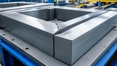
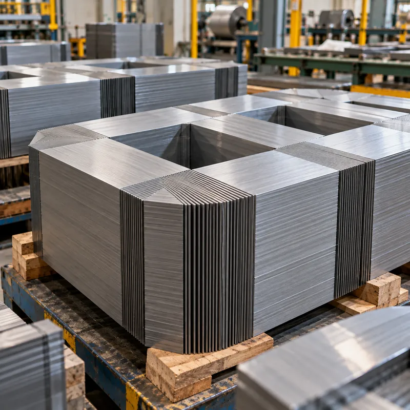
where A is the net core cross-section (gross area times stacking factor, typically 0.95–0.97 for laminations, further reduced by the fill of a stepped circular core).
What this tells a designer
- For a given voltage and frequency,
Bmax ∝ V / (f × N × A). More turns or more core area lower flux density. - Flux density is set by applied voltage, not by load current. Load current produces opposing ampere-turns in primary and secondary that cancel in the core, as described in our current transformer working principle article.
- Raising volts per hertz raises B in direct proportion. A 10% overvoltage raises B by 10%.
The same equation is used in reverse for winding design; see our transformer winding calculator guide for turns calculations at different voltages.
Choosing Flux Density in a Transformer Core
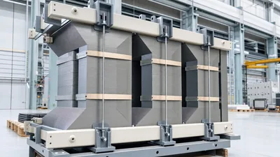
Core flux density is a design choice driven by core material, loss targets, noise limits and over-excitation requirements. The B–H curve of each material shows a knee beyond which permeability collapses and magnetizing current rises sharply; designers stay comfortably below it.
| Core material | Saturation B (approx.) | Typical design Bmax | Notes |
|---|---|---|---|
| Conventional grain-oriented silicon steel | 2.0 T | 1.5–1.7 T | Standard for distribution and power transformers |
| High-permeability / domain-refined GO steel | 2.0 T | 1.6–1.75 T | Lower losses, used for high-efficiency designs |
| Amorphous metal ribbon | about 1.56 T | 1.3–1.4 T | Very low no-load loss; larger core |
| Non-oriented silicon steel | about 1.9–2.0 T | 1.2–1.5 T | Motors, small transformers, reactors |
| Ferrite | 0.3–0.5 T | 0.1–0.3 T | High-frequency electronics only |
Higher flux density shrinks the core and copper but increases core loss roughly with B to a power between about 1.6 and 2, raises magnetostriction noise and lowers headroom against overvoltage. Lower B costs more steel. Our core lamination material guide and losses and total cost of ownership guide discuss how loss evaluation shifts that optimum.
Over-excitation limits
IEEE C57.12.00 requires transformers to operate at 105% of rated secondary voltage at rated load, and 110% at no load, without damage. The core must therefore be designed so that B at 110% voltage remains below the knee. Overexcitation can also come from low frequency: a 60 Hz transformer on a 50 Hz supply sees B increase by 60 / 50 = 1.2, or 20%, which typically drives it into saturation. See our 50 Hz vs 60 Hz guide.
Worked Example: Volts per Turn and Flux Density for a 1000 kVA Transformer
Design target: a 1000 kVA, 11 kV delta to 415 V wye, 50 Hz distribution transformer with a grain-oriented steel core at about 1.7 T.
- Net core area. Assume a stepped core of 220 mm circumscribing diameter. Gross circle area is
π × 0.11² = 0.0380 m²; with step fill and stacking factor of about 0.85 combined, net areaA ≈ 0.032 m². - Volts per turn at 1.7 T.
E / N = 4.44 × 50 × 1.7 × 0.032 = 12.08 V/turn. - LV turns. Phase voltage on the wye LV is
415 / √3 = 239.6 V, soN(LV) = 239.6 / 12.08 = 19.8, rounded to 20 turns. - Recalculate actual B.
B = 239.6 / (4.44 × 50 × 20 × 0.032) = 1.686 T. - HV turns. HV is delta, so phase voltage is 11,000 V:
N(HV) = 11,000 / 239.6 × 20 = 918 turnsat the principal tap. - Overvoltage check. At 110% voltage,
B = 1.10 × 1.686 = 1.85 T, still below the 2.0 T saturation level of grain-oriented steel but near the knee, which is why some purchasers specify 1.6 T or lower.
Rounding LV turns to an integer is why real designs adjust core area slightly to hit both a whole-number turns count and the target B. The numbers above are illustrative; actual designs also balance impedance, losses and short-circuit strength. For the core build itself see our transformer core engineering guide.
Flux Density, Inrush Current and Residual Flux
When a transformer is switched on, the flux must start from whatever residual value remains in the core. In the worst case, switching at a voltage zero with residual flux of the same polarity, peak flux can approach 2 × Bmax + Bresidual. With a design B of 1.7 T and residual 0.8 T, that would demand about 4.2 T, far above saturation, so the core saturates and the magnetizing current spikes to many times rated current for several cycles.
This is why:
- Lower design flux density reduces inrush magnitude.
- Protection relays use second-harmonic restraint to distinguish inrush from internal faults.
- Large transformers sometimes use controlled switching to energize at the optimum point on wave.
Our transformer inrush current guide covers typical inrush multiples and protection settings. Residual flux also distorts DC winding resistance tests, so commissioning engineers often demagnetize the core afterward.
Flux density concepts apply equally to inductors and reactors, where an air gap deliberately lowers effective permeability so the device stores energy without saturating; see our inductor vs transformer explainer.
Next Steps: Specifying and Sourcing
Buyers rarely need to specify core flux density directly, but it is legitimate to ask for it, and it reveals a lot about a design. In an RFQ for a distribution or power transformer, consider requesting:
- Rated flux density at nominal voltage and at maximum tap and 110% voltage.
- Core material grade and lamination thickness.
- Guaranteed no-load loss, no-load current and sound level, which are all driven by flux density.
- Over-excitation capability statement (for example 110% continuous at no load).
- Frequency: confirm 50 or 60 Hz explicitly, especially for export equipment.
MARS designs power transformers up to 31,500 kVA and 110 kV class, and oil-immersed distribution transformers, to IEC 60076 with ANSI/IEEE variants, for 50 and 60 Hz. Design data sheets including flux density and loss guarantees are provided with quotations, and every unit receives routine tests including no-load loss and current measurement. Send your specification through the quote request form.
Frequently asked questions
What is the difference between magnetic flux and magnetic flux density?
Magnetic flux is the total magnetic field passing through an area, measured in webers. Magnetic flux density is the flux per unit area perpendicular to the field, measured in teslas (T), where 1 T equals one weber per square meter. Flux density describes field concentration; flux describes the total quantity through a surface.
What is the symbol for magnetic flux?
Magnetic flux is represented by the Greek capital letter phi, Φ, sometimes written ΦB to make clear it is magnetic. Magnetic flux density uses the symbol B, and magnetic field strength uses H. Flux linkage, the flux multiplied by the number of turns it passes through, uses λ or Ψ.
What is magnetic flux measured in?
Magnetic flux is measured in webers (Wb) in the SI system. One weber equals one volt-second, or 1 T × 1 m². In the older CGS system flux is measured in maxwells, with one weber equal to 100 million maxwells.
How do you calculate magnetic flux through a coil?
For a uniform field, multiply flux density by the coil area and the cosine of the angle between the field and the coil's normal: Φ = B × A × cos θ. The flux linkage of a coil with N turns is N × Φ, and the induced voltage equals N times the rate of change of flux.
What flux density do transformer cores operate at?
Distribution and power transformers using grain-oriented silicon steel typically operate at 1.5 to 1.75 T at rated voltage, below a saturation level of about 2.0 T. Amorphous metal cores run lower, around 1.3 to 1.4 T, because they saturate near 1.56 T.
Why does flux density increase when frequency drops?
From the EMF equation, flux density equals voltage divided by 4.44 times frequency, turns and core area. At constant voltage, lowering frequency raises flux density proportionally. A transformer designed for 60 Hz operated at 50 Hz sees 20% higher flux density, which can saturate the core and overheat it.
Written and reviewed by the MARS application engineering team in Shanghai, who specify and test transformers, switchgear, substations and battery storage for projects in 40+ countries. Last updated .
Tags: magnetic flux density magnetic flux magnetic flux and flux density magnetic flux symbol what is magnetic flux measured in