Key takeaways
- A CT scales current by its turns ratio, so a 400:5 CT with one primary turn has 80 secondary turns and outputs 4 A when 320 A flows.
- Metering CTs use classes such as 0.2S or 0.5 under IEC 61869-2, or 0.3 and 0.15 under IEEE C57.13, with error limits defined over a stated current range, down to 1% of rated current for S classes.
- Protection CTs are rated 5P20 or 10P20 under IEC, or C200 to C800 under IEEE, meaning they hold accuracy during faults up to 20 times rated current.
- Burden in VA equals I² × R; at 5 A secondary, 0.275 Ω of lead resistance alone consumes about 6.9 VA, which is why long runs favor 1 A secondaries.
- An energized CT secondary must never be open-circuited, because the core saturates and dangerous peak voltages appear across the open terminals.
Quick answer: A current transformer works by ampere-turn balance: the primary conductor's current creates flux in a toroidal core, and the secondary winding drives an opposing current so that Ip × Np = Is × Ns. A 400:5 CT therefore delivers 5 A when 400 A flows in the primary, scaled down safely for meters and relays.
Every meter, protection relay and power-quality analyzer on a medium-voltage feeder relies on current transformers. They are passive, robust and inexpensive compared with the equipment they protect, yet a poorly chosen ratio, accuracy class or burden is enough to make a differential relay trip on through-faults or a revenue meter under-register for years.
This article explains what a current transformer means in practical terms, the physics of how it works, how ratio, taps and accuracy class are defined, how a CT is built and insulated, and how to calculate burden. It is aimed at electrical engineers, commissioning staff and buyers specifying CTs for switchgear, substations and power transformers.
What Is a Current Transformer?
A current transformer (CT) is an instrument transformer that produces a secondary current proportional to, and nearly in phase with, the current in its primary conductor, so that meters and relays can measure high currents safely. It isolates the measuring circuit from line voltage and standardizes the signal at 5 A or 1 A full scale.
A CT differs from a power transformer in one essential way. A power transformer is connected across a voltage source and its flux is set by that voltage. A CT is connected in series with the load: its primary current is set by the power system, not by the CT, and the CT secondary behaves as a current source. The secondary voltage rises only as high as needed to push the secondary current through the connected burden.
CTs sit alongside voltage transformers in the broader family covered in our instrument transformers engineering guide; our PT transformer guide covers the voltage side. Typical uses include:
- Revenue and check metering at utility interfaces.
- Overcurrent, earth-fault, distance and differential protection.
- Winding-temperature simulation and cooling control inside power transformers.
- Power-quality monitoring and energy management in LV switchboards.
How Does a Current Transformer Work? The Principle of Ampere-Turn Balance
The current transformer principle follows from Ampère's law and Faraday's law. Current in the primary conductor produces a magnetomotive force Fp = Np × Ip. With the secondary shorted through a low-impedance burden, the induced secondary current produces an opposing MMF Fs = Ns × Is. The two nearly cancel; only a small excitation MMF remains to magnetize the core:
Np × Ip = Ns × Is + Np × Ie
where Ie is the excitation current referred to the primary. In an ideal CT, Ie = 0 and Is = Ip × Np / Ns. In a real CT, excitation current is the source of both ratio error and phase displacement.
Why the core flux stays low
Because primary and secondary MMFs cancel, net core flux is small, just enough to induce the voltage Es = Is × (Rct + Zb), where Rct is the secondary winding resistance and Zb the burden. From the EMF equation Es = 4.44 × f × Ns × B × A, a low secondary voltage means low flux density. If burden or current rises, B rises; when it approaches saturation, excitation current grows rapidly and accuracy collapses. Our magnetic flux density guide explains that relationship.
Why an open secondary is dangerous
If the secondary is opened while primary current flows, there is no opposing MMF. All primary ampere-turns magnetize the core, which saturates every half cycle. The rapid flux reversals induce peak voltages that can reach several kilovolts, damaging insulation and endangering personnel. Always short the secondary at the test block before removing a meter or relay.
Current Transformer Ratio, CT Ratios and Taps
The current transformer ratio is the rated primary current divided by the rated secondary current, written as 400:5 or 400/1. For a window (toroidal) CT with the conductor passing through once, Np = 1, so Ns = Ip / Is; a 400:5 CT has 80 secondary turns.
Passing the primary through the window twice halves the effective ratio: the same 400:5 CT becomes 200:5. This trick is useful for small loads but changes the CT's rated short-time current per turn, so check before relying on it.
Current transformer taps
Multi-ratio (MR) CTs bring out taps on the secondary winding. A common IEEE C57.13 example is the 1200:5 MR bushing CT with taps giving 100, 200, 300, 400, 500, 600, 800, 900, 1000, 1100 and 1200:5. Accuracy class applies at the full winding; on lower taps the available voltage, and thus the relay class, falls in proportion to the turns used. A C400 rating at 1200:5 is roughly C200 on the 600:5 tap.
| Ratio | Secondary turns (Np = 1) | Secondary current at 80% load | Typical application |
|---|---|---|---|
| 100:5 | 20 | 4.0 A at 80 A | Small LV feeders |
| 400:5 | 80 | 4.0 A at 320 A | 250–300 kVA LV incomer |
| 1600:5 | 320 | 4.0 A at 1280 A | 1000 kVA LV main |
| 200:1 | 200 | 0.8 A at 160 A | 11 kV feeder protection |
| 1200:5 MR | 240 (full) | Tap-dependent | Power transformer bushings |
Choosing primary rating for normal load, fault level and relay settings is a topic of its own; see our CT ratio selection and sizing guide.
Current Transformer Accuracy Class and Classification
Accuracy class defines the maximum ratio error and phase displacement at specified currents and burdens. Current transformer classification splits into metering and protection classes, with IEC and IEEE using different notation.
| Standard | Class | Meaning | Typical use |
|---|---|---|---|
| IEC 61869-2 | 0.1, 0.2, 0.5, 1 | Ratio error limit in % at 100–120% rated current | Metering, instruments |
| IEC 61869-2 | 0.2S, 0.5S | Extended accuracy down to 1% of rated current | Revenue metering with wide load range |
| IEC 61869-2 | 5P20, 10P20 | Composite error ≤5% or ≤10% at 20 × rated current | Overcurrent, earth fault |
| IEC 61869-2 | PX, TPX, TPY, TPZ | Defined by knee-point voltage or transient performance | Differential, distance protection |
| IEEE C57.13 | 0.15, 0.3, 0.6, 1.2 | Metering accuracy at stated B-burden | Metering |
| IEEE C57.13 | C100–C800, T-class | Secondary terminal volts at 20 × rated current with ≤10% error | Relaying |
A C200 CT, for example, can deliver 20 × 5 A = 100 A into a 2.0 Ω standard burden (B-2.0) while keeping ratio error within 10%: 100 A × 2.0 Ω = 200 V. An IEC 5P20 CT with 15 VA rated burden holds 5% composite error at 20 times rated current with that burden connected.
Metering classes intentionally saturate early to protect meters during faults, so never use a metering core for protection. Multi-core CTs in switchgear typically have one metering core and one or two protection cores on the same primary. Field verification of class and ratio is covered in our current transformer testing guide.
Worked Example: Calculating CT Burden and Choosing VA
Burden is the total load on the CT secondary, expressed in ohms or in VA at rated secondary current: VA = Is² × Zb.
Scenario: a 400:5 protection CT in an 11 kV panel feeds a digital relay (0.5 VA at 5 A) and an ammeter (1 VA). The relay room is 20 m away, using 2.5 mm² copper, so the loop length is 40 m.
- Lead resistance: copper resistivity 0.0172 Ω·mm²/m gives
R = 0.0172 × 40 / 2.5 = 0.275 Ω. - Lead burden at 5 A:
5² × 0.275 = 6.9 VA. - Device burden:
0.5 + 1.0 = 1.5 VA. - Total:
6.9 + 1.5 = 8.4 VA. Select a 10 VA or 15 VA core, for example 15 VA 5P20.
Same circuit with 1 A secondary: lead burden is 1² × 0.275 = 0.275 VA. Device burden is similar for modern relays, so total is under 2 VA and a 5 VA core suffices. This is why 1 A secondaries are preferred for long cable runs in substations, while 5 A remains common inside LV switchboards with short wiring.
Check also the fault end. With 16 kA on a 400:5 CT (40 times rated), secondary current is 200 A. The 15 VA rated burden is 15 / 25 = 0.6 Ω; the actual burden is 8.4 / 25 = 0.336 Ω. With Rct = 0.2 Ω, the effective accuracy limit factor is ALF' = 20 × (0.2 + 0.6) / (0.2 + 0.336) ≈ 30, still below the 40 needed. Either confirm the relay tolerates saturation above its instantaneous setting, or specify a higher factor such as 5P40, or a PX core with a stated knee-point voltage.
Current Transformer Construction and Parts
Current transformer design balances core cross-section, turns and insulation against accuracy, short-time rating and cost. The main parts of a current transformer are:
- Core: usually a toroid of grain-oriented silicon steel for protection CTs, or nickel-iron or nanocrystalline alloy for high-accuracy metering CTs, because their high permeability reduces excitation current.
- Secondary winding: enameled copper wound evenly around the full toroid to minimize leakage flux and error.
- Primary: the power conductor itself (window or bar type) or a few turns of heavy conductor (wound type).
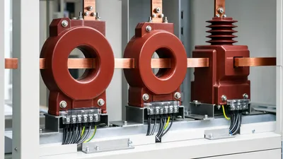
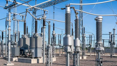
- Insulation: current transformer insulation must withstand the full system voltage between primary and secondary. LV CTs use thermoplastic housings; MV indoor CTs are cast in epoxy resin; HV outdoor CTs use oil-paper insulation in porcelain or composite housings, or SF6 gas.
- Terminals and short-circuit link: secondary terminals S1/S2 (IEC) or X1/X2 (IEEE), often with a shorting provision.
Types of current transformers
| Type | Construction | Where used |
|---|---|---|
| Window / toroidal | Core and secondary only; primary passes through | LV boards, cable earth-fault CTs |
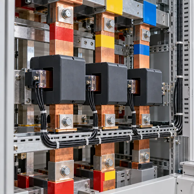
| Bar-primary | Built-in bar as one primary turn | MV switchgear, LV busbars |
| Wound-primary | Several primary turns | Low-ratio metering |
| Bushing | Toroid around a transformer or breaker bushing | Power transformers, dead-tank breakers |
| Split-core | Hinged core for retrofit | Monitoring without disconnection |
Core-balance CTs for sensitive earth-fault detection are covered in our core current transformer guide, and outdoor HV designs in our high-voltage current transformer guide.
Current Transformer Ratings to Specify
A complete set of current transformer ratings lets any manufacturer quote a compliant unit. Specify:
- Rated primary and secondary current: for example 400/5 A or 200/1 A, with taps if multi-ratio.
- Rated continuous thermal current: often 120% or 150% of rated primary (extended rating factor).
- Short-time thermal current (Ith): for example 25 kA for 1 s or 3 s, matching the switchgear rating.
- Dynamic current (Idyn): typically 2.5 × Ith peak for 50 Hz systems.
- Highest voltage for equipment (Um) and insulation level: for example 12 kV with 28 kV power-frequency and 75 kV lightning impulse withstand.
- Accuracy class and burden per core: for example core 1: 0.5S, 10 VA; core 2: 5P20, 15 VA.
- Knee-point voltage, Rct and excitation limits for PX cores used in differential protection.
- Frequency, mounting, terminal type and polarity marking.
Polarity marking (P1/P2 and S1/S2, or H1 and X1) matters for differential and directional schemes; our CT connection guide shows star and delta secondary connections and polarity checks.
Next Steps: Specifying and Sourcing
CTs are usually bought as part of the equipment they serve, so the cleanest approach is to specify them in the switchgear or transformer RFQ with a CT schedule per panel or bushing: ratio, class, burden, Ith and purpose (metering, overcurrent, differential, REF, winding temperature).
MARS power transformers up to 31,500 kVA and 110 kV class can be supplied with bushing CTs to your protection schedule, and our KYN28 metal-clad switchgear and ring main units include feeder CTs selected to the relay and metering requirements you specify. CT ratio and polarity checks are part of our routine and factory acceptance testing, and FAT witnesses are welcome. Share your single-line diagram and CT schedule through the quote request form.
Frequently asked questions
What does a current transformer mean in simple terms?
A current transformer is a device that reduces a large current, such as 1,000 A in a busbar, to a small proportional current, typically 5 A or 1 A, that meters and protection relays can measure safely. It also isolates those instruments from the high voltage of the power circuit.
How do you calculate a current transformer ratio?
Divide rated primary current by rated secondary current. A CT rated 600 A primary and 5 A secondary has a 600:5, or 120:1, ratio. To find primary current from a reading, multiply the secondary current by the ratio: 3.5 A on a 600:5 CT means 3.5 × 120 = 420 A in the primary.
What is the difference between 5P20 and C400 CT classes?
5P20 is an IEC 61869-2 protection class meaning composite error stays within 5% at 20 times rated current with rated VA burden connected. C400 is an IEEE C57.13 class meaning the CT can deliver 20 times rated current with at most 10% ratio error while developing 400 V at its terminals into standard burden.
Why must a CT secondary never be left open?
With the secondary open, nothing opposes the primary ampere-turns, so the core saturates every half cycle and the collapsing flux induces very high peak voltages across the open terminals. These can exceed several kilovolts, break down insulation and injure anyone touching the wiring. Short the secondary before disconnecting instruments.
What are the main types of current transformers?
The main types are window or toroidal CTs, bar-primary CTs, wound-primary CTs, bushing CTs mounted around transformer or breaker bushings, and split-core CTs for retrofit monitoring. They can also be classified by use, metering or protection, and by insulation, such as resin-cast, oil-paper or gas-insulated.
Should I choose a 1 A or 5 A CT secondary?
Choose 1 A when leads to the relay or meter are long, as in substations, because lead burden falls by a factor of 25 compared with 5 A. Choose 5 A for short wiring inside switchboards and where existing meters and relays are 5 A rated. Modern digital relays usually accept either.
Written and reviewed by the MARS application engineering team in Shanghai, who specify and test transformers, switchgear, substations and battery storage for projects in 40+ countries. Last updated .
Tags: how a current transformer works current transformer ratio current transformer accuracy class types of current transformers current transformer construction