Key takeaways
- Every current transformer connection must maintain a single-point secondary earth to eliminate ground loop circulating currents and prevent high-voltage coupling.
- Current transformer orientation dictates the phase angle of the secondary current, where reversing primary polarity orientation creates a 180-degree phase shift that trips differential relays.
- Secondary circuits must never be operated in an open-circuit state because unconstrained core flux generates destructive peak voltages exceeding several kilovolts.
- Total connected burden comprising relay internal impedance, terminal contact resistance, and two-way cable loop resistance must not exceed the CT rated volt-ampere capacity.
- Modern digital protection relays normally require a star (wye) current transformer connection, handling vector group compensation internally via firmware algorithms.
Quick answer: A current transformer connection couples the secondary terminals to protective relays or meters in series, matching primary line orientation to maintain precise phase relationships. Correct execution requires verified polarity, a dedicated single-point earth on the secondary loop, and strict avoidance of open-circuit conditions under load.
In electrical power distribution and transmission networks, instrument transformers step down high line currents to standardised 1 A or 5 A secondary values. Establishing an accurate current transformer connection is vital for the correct operation of overcurrent, earth-fault, distance, and differential protection schemes. When connections fail or secondary polarity is reversed, protection relays either fail to trip during genuine faults or misoperate during healthy load conditions.
Field commissioning engineers frequently encounter errors such as undersized secondary cabling, dual-point earthing that induces ground circulating currents, and incorrect bushing CT installation. This engineering guide examines standard wiring topologies, orientation rules, burden calculations, and commissioning verifications based on IEC 61869-2 and IEEE C57.13 specifications. For comprehensive transformer schemes, this guide complements our detailed analysis of transformer wiring schematic diagrams and system-level transformer protection design.
Understanding Current Transformer Orientation and Polarity
Proper current transformer orientation establishes the instantaneous direction of secondary current relative to the primary line current entering the equipment. Instrument transformers follow subtractive polarity rules governed by IEC 61869-2 clause 6.13 and IEEE C57.13 clause 6. Under these standards, when instantaneous primary current enters the marked primary terminal (P1 under IEC, or H1 under IEEE), the secondary current simultaneously leaves the corresponding marked secondary terminal (S1 under IEC, or X1 under IEEE).
Incorrect physical orientation of a window-type (ring-type) or bar-type CT flips the phase angle of the measured current by 180 degrees. While a simple analogue ammeter or thermal overload bimetal strip functions regardless of polarity, directional overcurrent relays (ANSI 67), distance relays (ANSI 21), and transformer differential schemes (ANSI 87T) will malfunction immediately. In a differential circuit, a single reversed CT secondary treats normal through-load current as an internal phase-to-phase fault, triggering an instantaneous transformer trip.
Engineers must verify both primary and secondary markings prior to landing conductors:
- IEC Nomenclature: Primary terminals are designated P1 (line/supply side) and P2 (load side). Secondary windings are labelled S1 (entering polarity) and S2 (outgoing return). Multi-ratio secondaries add intermediate taps designated S3, S4, or S5.
- IEEE / ANSI Nomenclature: Primary terminals are designated H1 and H2. Secondary terminals use X1, X2, X3, and X4 designations.
- Bushing CT Positioning: On power transformers and metal-clad switchgear, ensure the physical polarity face (usually stamped with a dot or polarity marking) points toward the designated protected zone rather than the external bus.
Interpreting the Current Transformer Wiring Diagram for Protection and Metering
Reading a current transformer wiring diagram correctly requires distinguishing between metering cores and protection cores on multi-core assemblies. Modern medium-voltage and high-voltage switchgear installations deploy multi-ratio CTs containing independent magnetic cores stacked within a single cast-resin or oil-filled housing. Each core possesses distinct saturation characteristics and accuracy classes engineered specifically for its intended duty.
Metering cores (such as Class 0.2S or Class 0.5 per IEC 61869-2 Table 201) feature an Instrument Security Factor (FS) typically rated at FS 5 or FS 10. These cores are designed to saturate at modest overcurrents (5 to 10 times rated current) to shield sensitive downstream energy meters and transducers from thermal and dielectric damage during grid faults. Conversely, protection cores (such as Class 5P20, Class 10P20, or IEEE Class C800) maintain linear transformation up to 20 or 30 times rated current without core saturation, ensuring relays accurately calculate high-magnitude fault dynamics.
On engineering schematics, wiring runs from secondary terminals through isolation test blocks before reaching protection devices. The test block permits technicians to insert shorting pins prior to disconnecting any secondary instrument. In switchgear assemblies detailed in our substation protection and relay guide, CT secondaries must route cleanly through dedicated marshalling boxes with shorting-type disconnect terminal blocks to facilitate maintenance without interrupting live primary plant.
Current Transformer Connection Configurations in Three-Phase Systems
Three-phase current transformer connection schemes vary according to system earthing methods, protective relay architectures, and legacy electromechanical constraints. While modern numerical relays perform mathematical phase shifting and zero-sequence filtering within relay software, the physical hardwiring must follow strict topological rules. The table below compares the primary three-phase secondary connections encountered in industrial and utility distribution systems.
| Configuration | Secondary Interconnection | Residual / Neutral Path | Phase Shift Secondary vs Primary | Primary Applications |
|---|---|---|---|---|
| Four-Wire Star (Wye) | S2 (or X2) terminals of all three phases bonded together into neutral bus | Neutral conductor carries vector sum ($I_A + I_B + I_C$) to earth-fault element | 0° (in-phase) | Numerical protection relays, comprehensive revenue metering, feeder overcurrent |
| Three-Wire Delta | S2 of Phase A connected to S1 of Phase B, S2 of B to S1 of C, S2 of C to S1 of A | Traps zero-sequence (triplen harmonic) currents within the closed delta loop | 30° or 210° (depending on standard or reverse delta) | Legacy electromechanical transformer differential schemes on Dy or Yd transformers |
| Holmgreen Residual Connection | Three CT secondaries connected in parallel across a single relay element | Monitors residual current directly ($3I_0$) through dedicated earth-fault relay | 0° | Solidly earthed or low-resistance earthed neutral systems lacking 4-wire relays |
| Open-Delta (V-Connection) | Two CTs installed on phases A and C; phase B current derived algebraically | No neutral or earth fault measurement capability | 0° on instrumented phases | Low-voltage ungrounded distribution systems, motor branch circuits, economic metering |
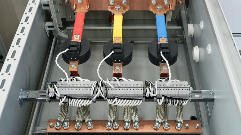
When implementing a star current transformer connection, the S2 (X2) terminals are tied together to form a common star point. This star point must connect to the substation earth grid at exactly one point. If multiple grounds are installed—for example, one ground inside the switchgear cubicle and another at the relay control panel—stray ground-potential differences induce circulating currents through the CT neutral lead, falsifying measurement readings and destabilising sensitive differential schemes.
Worked Engineering Calculation: CT Secondary Burden and Cable Sizing
A CT secondary circuit must maintain total impedance below the transformer rated burden to avoid early saturation during high-magnitude short circuits. In this practical engineering calculation, we evaluate a 2000/5 A, Class 5P20, 15 VA protection CT installed inside 11 kV switchgear supplying a multi-function protection relay located in a remote control room panel. The single-phase one-way cable length is 45 metres using standard 4.0 mm² copper conductor.
First, calculate the total circuit resistance. The loop length involves both the out-and-return conductor paths ($2 \times 45\text{ m} = 90\text{ m}$). Using the resistivity of copper at maximum operating temperature (75 °C), $\rho = 0.0216\ \Omega\cdot\text{mm}^2/\text{m}$:
$$R_{\text{cable}} = \frac{\rho \times L_{\text{loop}}}{A} = \frac{0.0216 \times 90}{4.0} = 0.486\ \Omega$$
Next, sum the components of the total secondary loop impedance ($Z_{\text{total}}$):
- Cable loop resistance ($R_{\text{cable}}$): $0.486\ \Omega$
- Relay current input impedance ($Z_{\text{relay}}$): $0.020\ \Omega$ (typical numerical relay current channel)
- Terminal block and test switch contact resistance ($R_{\text{contacts}}$): $0.050\ \Omega$
- CT secondary internal winding resistance ($R_{\text{ct}}$ at 75 °C): $0.150\ \Omega$
The external connected burden impedance is:
$$Z_{\text{ext}} = R_{\text{cable}} + Z_{\text{relay}} + R_{\text{contacts}} = 0.486 + 0.020 + 0.050 = 0.556\ \Omega$$
Now determine the operating volt-ampere burden at rated secondary current ($I_s = 5\text{ A}$):
$$S_{\text{connected}} = I_s^2 \times Z_{\text{ext}} = 5^2 \times 0.556 = 13.90\text{ VA}$$
Because the calculated connected burden (13.90 VA) is lower than the CT rated burden (15 VA), the installation complies with accuracy parameters under steady-state conditions. Next, verify the actual Accuracy Limit Factor ($ALF_{\text{actual}}$) during a 20 kA primary fault ($10 \times I_{\text{rated}}$) using the standard relation from IEC 61869-2 clause 5.6.201:
$$ALF_{\text{actual}} = ALF_{\text{rated}} \times \frac{R_{\text{ct}} + R_{\text{rated}}}{R_{\text{ct}} + Z_{\text{ext}}}$$
Where $R_{\text{rated}} = \frac{S_{\text{rated}}}{I_s^2} = \frac{15}{25} = 0.600\ \Omega$. Substituting the values:
$$ALF_{\text{actual}} = 20 \times \frac{0.150 + 0.600}{0.150 + 0.556} = 20 \times \frac{0.750}{0.706} = 21.24$$
The effective saturation margin ($ALF_{\text{actual}} = 21.24$) exceeds the nominal factor of 20, demonstrating that the 4.0 mm² cable maintains linear response beyond the prospective symmetrical fault level. Had 2.5 mm² cable been selected, cable resistance would have risen to $0.778\ \Omega$, pushing total external burden to 21.2 VA and reducing $ALF_{\text{actual}}$ to 16.1, which causes dangerous waveform clipping and delayed relay operation during heavy faults.
Safe Current Transformer Connection and Commissioning Checklist
Commissioning technicians must follow a structured procedure to verify secondary circuit integrity before energising primary switchgear or power transformers. Never open-circuit a live current transformer secondary; because primary current is imposed by the system load, an open secondary eliminates demagnetising ampere-turns, driving core flux density immediately into deep saturation and inducing narrow, lethal voltage spikes that exceed 3 kV to 5 kV across secondary terminals.
Engineers must execute the following commissioning steps sequentially:
- Perform Insulation Resistance (Megger) Testing: Disconnect the secondary earth link. Test insulation resistance between CT secondary wiring and earth using a 500 V or 1000 V DC insulation tester per IEEE C57.13.1. Minimum acceptable resistance is 10 MΩ. Re-establish the single-point earth link immediately following test completion.
- Verify DC Polarity via Flick Test: Connect an analogue moving-coil voltmeter across the secondary terminals. Momentarily tap a 9 V DC battery across the primary terminals (positive terminal to P1). A momentary positive (upscale) deflection confirms correct polarity marking and terminal identification.
- Perform Secondary Winding and Loop Resistance Measurements: Measure secondary winding resistance and total loop resistance using a calibrated micro-ohmmeter. Compare measured values against manufacturer factory test certificates to detect high-resistance crimps or loose screw terminals.
- Conduct Knee-Point Voltage and Excitation Checks: Inject AC voltage directly onto the secondary winding with primary open. Record magnetising current up to the saturation knee-point. Ensure knee-point voltage matches design parameters and compare results against benchmarks described in our power transformer testing procedures.
- Execute Primary Current Injection: Inject high-magnitude test current (e.g., 200 A to 800 A) through the primary busbar loop. Read secondary currents at the protection relay terminals to confirm ratio accuracy, phase sequence, and proper differential spill current balance.
Next steps: specifying and sourcing
When specifying current transformers for medium-voltage switchgear, containerised substations, or outdoor power transformers, clear documentation prevents manufacturing delays and site rework. Ensure your tender requisitions explicitly state system primary voltage, basic impulse level (BIL), continuous thermal current rating factor, primary-to-secondary turns ratio, secondary rating (1 A vs 5 A), core accuracy class (e.g., 0.2S for revenue metering; 5P20 or Class C for protection), and maximum anticipated external burden.
For projects requiring integrated medium-voltage equipment, browse our engineered HV/LV switchgear solutions, examine our robust power transformer equipment, or review factory-wired prefabricated transformer substations. To discuss application-specific CT core matching, relay coordination curves, or to submit your project single-line diagram for review, submit your technical requirements directly via our transformer quotation request page.
Frequently asked questions
What happens if a current transformer connection has reversed polarity?
Reversing current transformer polarity causes a 180-degree phase shift in the secondary current relative to the primary line. Directional overcurrent relays will fail to detect forward faults or trip incorrectly on reverse faults, while transformer differential relays will register through-load current as an internal fault and trip instantaneously.
Why must current transformer secondary circuits be earthed at only one point?
Earthing a CT secondary at only one point prevents earth circulating currents caused by ground potential differences between separate physical locations. Multiple earthing points create parallel paths that divert secondary current away from measuring relays, leading to metering inaccuracies and unwanted differential relay operations.
Why is opening a current transformer secondary circuit dangerous?
Opening a live CT secondary removes opposing secondary demagnetising ampere-turns, allowing primary current to drive core flux into extreme saturation. This rapid flux collapse during every alternating current half-cycle induces lethal peak voltages exceeding several thousand volts, creating severe flashover and electrocution hazards.
What is the difference between a 1 A and 5 A current transformer connection?
A 1 A secondary current transformer connection is engineered for long cable runs between switchgear and remote control rooms because cable lead burden losses ($I^2R$) are 25 times lower than in a 5 A secondary circuit. A 5 A connection is common in compact switchgear where relays are situated directly adjacent to the CTs.
Can you connect metering and protection relays to the same CT winding?
Connecting metering and protection devices to the same CT core is discouraged because protection cores do not saturate early enough to protect sensitive instruments during faults, while metering cores saturate too early for relays to measure fault currents. Modern practice specifies separate dedicated cores within the same CT assembly.
How do you verify the current transformer orientation during commissioning?
Current transformer orientation is verified using a DC voltage flick test or secondary injection testing. Tapping a DC voltage source across primary terminals induces an upscale deflection on a moving-coil analogue meter connected across secondary terminals, confirming that terminal markings match internal winding polarity.
Tags: current transformer connection current transformer wiring diagram current transformer orientation ct secondary wiring instrument transformer


