Key takeaways
- Instrument transformers step down high voltages and currents to standardised, safe secondary values (typically 1 A or 5 A, and 100 V or 110 V) for protection relays and revenue metering.
- Metering cores require high precision at normal operating load and early saturation to safeguard sensitive instruments, whereas protection cores demand linear response up to fault levels 20 to 30 times rated current.
- Accuracy classes defined by IEC 61869 and IEEE C57.13 dictate permissible ratio error and phase displacement across specific secondary burden ranges.
- High voltage instrument transformers utilise oil-paper, gas-insulated (SF6), or cycloaliphatic outdoor resin insulation to withstand steep lightning impulse withstand levels (BIL) and harsh environmental pollution.
- Proper secondary burden matching is critical because an oversized burden degrades ratio accuracy, while an open-circuited current transformer develops lethal peak voltages across its terminals.
Quick answer: Instrument transformers are high-accuracy electrical devices designed to scale down high transmission and distribution voltages and currents to standardised, galvanically isolated secondary values (such as 110 V, 1 A, or 5 A) for protection relays, energy meters, and control apparatus.
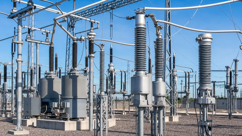
Modern electrical grids operate at potential levels reaching hundreds of kilovolts and short-circuit fault levels exceeding tens of kiloamperes. Direct connection of secondary control gear, digital disturbance recorders, or revenue meters to such potentials is technically unfeasible, economically prohibitive, and hazardous to personnel. By converting primary system parameters into proportionate, low-level secondary signals, instrument transformers form the sensory baseline of switchgear, substations, and industrial networks. Whether incorporated within HV/LV switchgear assemblies or erected as standalone yard apparatus in a transformer substation, their performance determines whether downstream protective relays clear faults in cycles or fail to trip altogether.
What are instrument transformers and how do they function?
Instrument transformers operate on Faraday’s law of electromagnetic induction to replicate primary line current and voltage waveforms at a precise, scaled down ratio with minimal phase displacement. Unlike standard power transformers engineered to transfer substantial continuous bulk energy (as detailed in our transmission transformer engineering guide), instrument transformers transfer minimal power—often less than 30 VA—prioritising signal fidelity, linearity, and phase angle precision over power conversion efficiency.
An instrument transformer achieves galvanic isolation between the primary high-voltage conductor and secondary circuits connected to ground. This protects human operators and digital secondary equipment from direct system voltages, transient overvoltages, and ground potential rise. In AC networks, these devices fall into two fundamental operational categories: current transformers (CTs), which connect in series with the line to sample current, and voltage transformers (VTs or potential transformers, PTs), which connect in shunt across phases or from phase to earth to sample electrical potential.
Types of instrument transformers products: CTs, VTs, and combined units
Instrument transformers products are engineered across three principal topologies: current sensing, inductive or capacitive voltage sensing, and combined metering units that house both functions in a singular enclosure.
Depending on grid topology, engineers select from the following configurations:
- Current Transformers (CT): Designed with a primary winding (either a single bar/bushing pass or multiple turns) and a secondary winding wrapped around a toroidal magnetic core. CTs deliver a secondary current proportional to the primary line current, standardised universally at either 1 A or 5 A.
- Inductive Voltage Transformers (IVT): Constructed similarly to conventional step-down transformers, utilizing magnetic steel cores and copper windings. They deliver precision transformation up to roughly 145 kV, stepping down line voltages to typical secondary levels of 100 V, 110 V, or 120 V phase-to-phase (or 110/√3 V phase-to-neutral).
- Capacitor Voltage Transformers (CVT): Applied predominantly on high voltage networks exceeding 110 kV up to 765 kV. A CVT combines a capacitive voltage divider with an intermediate inductive electromagnetic unit. This design reduces insulation volume and expense while serving a dual purpose by coupling high-frequency carrier signals (PLC) for grid communications.
- Combined Metering Units: Units housing both CT and VT elements inside a singular oil-filled or cast-resin enclosure. These compact packages reduce substation footprint and civil footing costs, especially in renewable energy collector stations and revenue boundary points.
Key technical specifications for instrument transformer equipment
Specifying instrument transformer equipment requires balancing electrical insulation withstand, thermal limits, accuracy limits, and secondary burden capabilities.
International standards—principally IEC 61869-1, IEC 61869-2 (CTs), IEC 61869-3 (Inductive VTs), and IEEE C57.13—define performance through distinct operational parameters:
| Parameter | Current Transformers (CT) | Voltage Transformers (VT) | Engineering Significance |
|---|---|---|---|
| Rated Ratio | e.g., 600/5 A, 1200/1 A, 2000-4000/1 A | e.g., 33000/√3 to 110/√3 V | Establishes primary-to-secondary scaling for relays and digital instruments. |
| Accuracy Class (Metering) | 0.1, 0.2, 0.2S, 0.5, 0.5S | 0.1, 0.2, 0.5 | Guarantees minimal ratio and phase errors across 1% to 120% rated current (0.2S extended range). |
| Accuracy Class (Protection) | 5P10, 5P20, 10P20, Class PX | 3P, 6P | Maintains linearity under short-circuit conditions without magnetic core saturation. |
| Rated Burden | 2.5 VA, 5 VA, 15 VA, 30 VA | 10 VA, 25 VA, 50 VA, 100 VA | The maximum external secondary load (loop impedance) without exceeding accuracy limits. |
| Thermal Short-Time Current | Ith (e.g., 40 kA for 1 s or 3 s) | N/A (Fuse protected / voltage rated) | Thermal withstand against fault current until upstream circuit breakers trip. |
| Dynamic Peak Current | Idyn = 2.5 × Ith | N/A | Mechanical withstand against severe electromagnetic forces during peak fault onset. |
For protection CT applications, the accuracy limit factor (ALF) defines saturation headroom. A 5P20 CT, for instance, maintains composite error below 5% when carrying 20 times its rated primary current, provided secondary burden limits are respected. For differential protection, Class PX (or Class X under BS 3938) mandates a defined knee-point voltage (Vk), maximum magnetising current, and secondary winding resistance ($R_{ct}$) to coordinate with transformer protection schemes.
Design considerations for high voltage instrument transformers
High voltage instrument transformers require robust dielectric designs to handle sustained line potentials, severe transient surges, and harsh environmental pollution.
As operating potentials ascend beyond 33 kV into transmission brackets (110 kV, 220 kV, 400 kV+), the design of insulation systems becomes paramount. A primary consideration is balancing internal dielectric medium choices:
- Oil-Paper Insulation: Highly refined, degassed mineral oil paired with high-density kraft paper. Excellent dielectric endurance and natural self-healing characteristics, though requiring continuous hermetic sealing with metal bellows to prevent moisture ingress. Routine verification is aligned with practices covered in our guide on transformer testing.
- Cast Epoxy Resin: Cycloaliphatic or polyurethane systems, dominant in indoor applications and outdoor distribution switchgear up to 36 kV. Eliminates liquid fire risks, allows mounting in arbitrary orientations, and needs virtually zero maintenance.
- Gas Insulation (SF6 or Gas Mixtures): Used in outdoor standalone designs or directly integrated into gas-insulated switchgear (GIS). Provides compact geometry, non-flammability, and elevated seismic tolerance.
External insulation must satisfy site-specific creepage requirements (often 25 mm/kV or 31 mm/kV for high-pollution coastal or industrial zones) using high-grade porcelain or hydrophobic silicone composite insulators. Furthermore, transient insulation must align with grid Basic Impulse Insulation Levels (BIL); a 110 kV class VT, for example, typically mandates a 550 kV lightning impulse withstand, operating reliably in parallel with large power transformers.
Engineering selection and sizing procedure for instrument transformers
Sizing instrument transformers requires a systematic engineering routine that accounts for primary system fault calculations, secondary cable lengths, and instrument power consumption.
Follow this five-step engineering workflow when sizing and specifying units:
- Determine Nominal and Maximum Primary Parameters: Calculate rated primary continuous current ($I_n$) and continuous operating voltage ($V_n$). Identify the maximum three-phase symmetrical short-circuit current ($I_{sc}$) and fault duration (e.g., 31.5 kA for 1 second) from system short-circuit studies.
- Select Core Quantities and Functions: Segregate metering and protection tasks onto dedicated, isolated secondary cores. Never mix revenue metering with protection relays on the same secondary core; metering cores are designed to saturate early to protect instruments, whereas protection cores must avoid saturation under high faults.
- Calculate Secondary Loop Burden: Sum the continuous burdens of connected relays, meters, auxiliary transducers, plus the two-way loop resistance of secondary copper cabling: $R_{loop} = 2 \cdot \rho \cdot \frac{L}{A}$. Ensure total burden does not exceed the CT or VT rated VA nameplate.
- Verify CT Knee-Point Voltage and Saturation Limits: For protective relays, apply the knee-point criteria: $V_k \ge K \cdot I_{fault\_sec} \cdot (R_{ct} + R_{loop} + R_{relay})$, where $K$ is the application-specific dimensioning factor (accounting for DC offset and system $X/R$ ratios). Consult our high voltage transformer guide for further analysis on transient system behaviour.
- Establish Dielectric and Installation Envelope: Match rated power frequency withstand and lightning impulse levels (BIL) to network standards. Confirm clearance dimensions, terminal stud sizing, temperature classes (-40°C to +55°C), and creepage distance.
How to select an instrument transformers solutions provider
A reliable instrument transformers solutions provider must demonstrate end-to-end manufacturing competence, adherence to international testing standards, and field-proven reliability under extreme grid operations.
When vetting international manufacturers and B2B suppliers, scrutinise the following technical criteria:
- Independent Type Test Certification: Ensure the factory provides accredited third-party test reports (such as KEMA, CESI, or equivalent accredited laboratories) validating short-time thermal and dynamic withstand, temperature rise, lightning impulse, and seismic performance.
- Partial Discharge (PD) Verification: Routine test certificates must prove low partial discharge levels (typically < 5 pC for cast resin, < 10 pC for oil-paper at 1.2 × Um/√3), verifying that the insulation contains no internal voids that cause gradual dielectric breakdown.
- Accuracy Testing Infrastructure: Confirm the factory utilises automated test benches capable of micro-calibrating phase error and ratio error curves across the entire operational range (1% to 120% for 0.2S metering cores) in strict accordance with IEC 61869 standards.
- Manufacturing Environment: High-voltage insulation processing demands controlled cleanrooms, vacuum drying chambers, and automated resin degassing units to guarantee homogeneous dielectric properties.
Next steps: specifying and sourcing
Specifying the correct instrument transformers requires precise coordination between grid fault capacity, protection relay curves, and physical switchgear constraints. To receive a detailed engineering proposal and commercial offer, compile your project Single Line Diagram (SLD), system rated voltage, required CT/VT ratios, accuracy classes, rated burdens, and environmental conditions. Our technical engineering team reviews complex grid and substation requirements to match exact application needs. Visit our power transformers portfolio or explore complete integrated options via our HV/LV switchgear solutions, and submit your technical specifications directly through our quote request form or contact page.
Frequently asked questions
What is the primary difference between a CT and a VT?
A current transformer (CT) connects in series with the power line to measure current by stepping it down to 1 A or 5 A, whereas a voltage transformer (VT) connects in shunt across phases or phase-to-ground to step high line voltages down to standard secondary values like 110 V.
Why must a current transformer secondary never be open-circuited while energized?
Operating a CT secondary open-circuited removes the counteracting secondary demagnetising flux, causing all primary current to act as magnetising current. This drives the iron core into heavy saturation, generating lethal kilovolt-range peak voltages across secondary terminals and causing catastrophic thermal insulation failure.
What is the difference between a 0.2 and a 0.2S accuracy class CT?
The 0.2S class provides an extended precision range for revenue metering, maintaining an accuracy of 0.2% down to 20% of rated current and retaining calibrated limits down to 1% current. Standard 0.2 class CTs are only certified for accuracy down to 5% of rated current.
What does CT burden mean and how does it affect performance?
CT burden is the total secondary circuit impedance expressed in ohms or volt-amperes (VA) at rated current, comprising connected meters, relays, and connecting lead wires. If the total connected burden exceeds the CT rating, core saturation occurs prematurely, causing severe ratio and phase angle errors.
When should capacitive voltage transformers (CVT) be chosen over inductive VTs?
Capacitive voltage transformers become economically and technically advantageous at transmission voltages of 110 kV and above. They reduce high-voltage insulation costs, occupy less physical space, and permit power line carrier (PLC) signal coupling for grid telecommunications and line differential protection.
Can a single instrument transformer core serve both metering and protection relays?
No, metering and protection functions must utilise separate cores because they have opposing saturation requirements. Metering cores must saturate at low fault currents to protect delicate digital meters, whereas protection cores must remain completely linear up to severe fault currents to guarantee relay operation.
Tags: instrument transformers instrument transformer equipment instrument transformers solutions provider instrument transformers products high voltage instrument transformers


