Key takeaways
- A high voltage transformer typically operates on transmission and sub-transmission systems at nominal operating voltages from 35 kV up to 765 kV.
- Basic Impulse Insulation Level (BIL) ratings define the dielectric withstand capability of high tension transformer windings against lightning and switching surges according to IEC 60076-3.
- High voltage voltage transformers (instrument VTs) step down line voltages to 100 V or 110 V for metering and protection, differing functionally from bulk high voltage power transformers.
- HV to HV transformer interties often employ autotransformer topologies with tertiary delta windings when voltage ratios are below 3:1 to minimise core losses and capital expenditure.
- Routine dielectric acceptance tests for any modern HV transformer require partial discharge monitoring maintained strictly below 100 pC at 1.5 times nominal line-to-earth voltage.
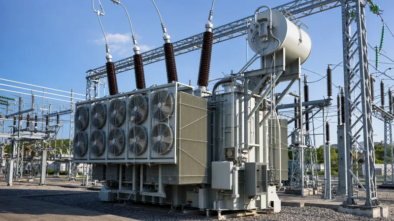
Quick answer: A high voltage transformer is an electromagnetic apparatus designed to step voltage levels up or down within transmission and sub-transmission networks, operating at system voltages from 35 kV up to 765 kV and above. It provides bulk power transfer, voltage regulation, and galvanic isolation across utility grids and heavy industrial complexes.
In alternating current power infrastructure, transmitting bulk electrical energy over extended physical distances demands elevated voltages to minimise resistive I²R line losses. Historically termed a high tension transformer in regional grid standards, the apparatus acts as the critical node linking generation assets, regional transmission rings, and primary distribution substations. Engineering these units requires meticulous calculation of dielectric clearances, thermal dissipation under dynamic load cycles, and transient withstand capability against lightning surges and system switching events.
For electrical consultants, substation design engineers, and procurement managers, specifying a high voltage power transformer involves balancing capital cost against long-term operational efficiency. This technical guide examines classification boundaries, dialectric insulation levels, structural core and winding architectures, and verification testing procedures mandated under international standards such as IEC 60076 and IEEE C57.12.00.
What Is a High Voltage Power Transformer? Engineering Classifications
A high voltage power transformer is categorised by its ability to transfer bulk apparent power across transmission voltages, usually rated from 10 MVA to upwards of 500 MVA three-phase. While medium-voltage distribution units step down electricity directly to industrial utilisation voltages (typically 400 V to 33 kV), an HV power transformer manages bulk intertie exchange between grid voltage tiers, as detailed in our comprehensive transmission transformer engineering guide.
Standard international classifications divide high-voltage apparatus into specific nominal voltage tiers:
- Sub-transmission Class (35 kV to 69 kV): Commonly deployed at regional utility nodes and industrial intake substations stepping down to distribution feeders.
- High Voltage Class (110 kV to 230 kV): Serves as the primary bulk transmission Backbone, linking generation plants to metropolitan ring substations.
- Extra-High Voltage (EHV: 345 kV to 765 kV): Used for long-distance bulk inter-regional transmission where minimizing thermal losses is paramount.
Under IEC 60076-1, high voltage apparatus must withstand continuous maximum operating voltages ($U_m$) typically 5% to 10% above the nominal operating level. For example, a nominal 110 kV network specifies an equipment highest voltage rating of 123 kV to maintain system stability during off-peak voltage rise scenarios.
HV Voltage Transformer vs HV Power Transformer: Resolving the Terminology
The phrase high voltage voltage transformer refers specifically to an instrument transformer (VT or PT) deployed for instrumentation and relay protection, whereas an HV power transformer handles bulk power transmission. Confusing these two distinct assets leads to procurement and design specification errors.
An instrument high voltage voltage transformer converts system voltages (such as 110 kV or 220 kV) into standardised, galvanically isolated low voltages—precisely 100 V, 110 V, or 115 V phase-to-phase. These low secondary signals feed protective relays, power quality meters, and SCADA monitoring units. They are rated in terms of burdens (volt-amperes, often between 10 VA and 200 VA) and accuracy classes (such as Class 0.2S for revenue metering or Class 3P for protection) governed by IEC 61869-3.
In contrast, a bulk hv transformer transfers continuous megawatts of operational energy through heavy copper conductors and complex oil-directed cooling channels. While an instrument VT uses inductive magnetic cores or capacitive divider circuits (CVTs) designed entirely around ratio accuracy and negligible phase displacement, an HV power transformer is engineered around thermal capacity, short-circuit mechanical strength, and loss capitalisation.
Configurations: Step-Up, Step-Down, and HV HV Transformer Interties
System design dictates whether an HV asset operates in step-up, step-down, or autotransformer configuration to match grid phase angles and system earthing policies. Selecting the appropriate winding architecture ensures overall network stability and mitigates zero-sequence harmonics.
Generation facilities require generator step-up (GSU) transformers to elevate machine terminal voltages (typically 11 kV to 24 kV) directly up to grid levels (110 kV to 400 kV). These units undergo extreme thermal loading and severe thermal cycling. Conversely, sub-transmission substations deploy step-down transformers to bring voltages down to distribution levels, frequently employing On-Load Tap Changers (OLTC) with a regulation range of ±10% to ±16% in 1.25% or 1.5% voltage steps.
In grid interconnect applications where the primary and secondary voltages are relatively close—such as a 400 kV to 220 kV or 230 kV to 115 kV substation—an hv hv transformer is frequently engineered as an autotransformer. Because the primary and secondary windings share a common physical section, physical size, weight, and copper losses are reduced substantially compared to a two-winding isolated transformer. When deploying HV autotransformers, a delta-connected tertiary winding is almost universally incorporated to circulate third-harmonic zero-sequence currents, suppress neutral instability, and provide auxiliary station power.
Dielectric Insulation, BIL Ratings, and Technical Specifications
Insulation integrity governs the design and operational lifespan of any high voltage transformer, demanding rigorous verification of internal clearances, oil dielectric strength, and paper degradation states. Designers balance liquid-dielectric chemistry with solid kraft insulation to achieve mandated Basic Impulse Insulation Levels (BIL).
The structural core and winding geometry must withstand elevated electric stress fields without generating localized ionization. To avoid insulation breakdown, engineers consult detailed guides on transformer internal components and insulation systems when specifying solid-to-liquid barrier ratios. Bushings must be specified with capacitive grading (OIP, RIP, or RIS type) for ratings of 69 kV and above to linearly distribute radial electric field gradients across the tank wall interface.
The table below provides typical baseline engineering parameters for standard three-phase oil-immersed high voltage power transformers constructed under IEC standards:
| Nominal Voltage Tier (kV) | Equipment Max Voltage Um (kV) | Typical Power Range (MVA) | Standard Lightning BIL (kV Peak) | Impedance %Z (IEC Baseline) | Standard Cooling Class |
|---|---|---|---|---|---|
| 35 | 40.5 | 10 – 40 | 200 | 7.5 – 9.0 | ONAN / ONAF |
| 66 / 69 | 72.5 | 20 – 80 | 325 / 350 | 8.0 – 10.5 | ONAN / ONAF |
| 110 / 115 | 123 | 31.5 – 120 | 450 / 550 | 10.0 – 12.5 | ONAF / OFAF |
| 132 / 138 | 145 | 40 – 160 | 650 | 11.0 – 13.5 | ONAF / ODAF |
| 220 / 230 | 252 | 63 – 240 | 950 / 1050 | 12.5 – 15.0 | ODAF / ODWF |
Correctly calculating percentage impedance (%Z) is critical for system coordination: higher impedance suppresses prospective short-circuit fault currents downstream, but causes greater internal voltage drop under full inductive loading.
Testing and Verification Standards for High Tension Transformers
Stringent factory acceptance testing (FAT) is mandatory to verify that an hv power transformer satisfies its guaranteed loss figures, dielectric margins, and dynamic mechanical robustness. Testing regimes must conform strictly to IEC 60076-3 or IEEE C57.12.90, as outlined in our manual on how to test a transformer.
Commissioning an HV asset requires an exhaustive series of sequential electrical and physical diagnostic procedures:
- Winding Resistance and Voltage Ratio Verification: Measuring DC resistance across all tap positions with Kelvin bridge circuits to verify winding balance, alongside turns-ratio and vector group verification (e.g., YNd11 or YNyn0).
- Dielectric Loss Dissipation (Tan Delta / Power Factor): Quantifying dielectric losses in both the winding insulation bulk and condenser bushings, with acceptable Tan Delta limits typically staying below 0.5% at 20°C.
- Applied and Induced Overvoltage Testing: Subjecting windings to applied separate-source AC withstand tests, followed by an induced overvoltage withstand test at double rated voltage (typically 100 Hz to 200 Hz) to avoid core saturation.
- Partial Discharge (PD) Measurement: Monitoring high-frequency electrical emissions concurrently during long-duration induced overvoltage (ACLD) testing; baseline partial discharge must remain strictly below 100 pC at 1.5 Um / √3.
- Full-Wave and Chopped-Wave Lightning Impulse Tests: Applying 1.2/50 µs high-voltage impulses directly to HV bushings to verify the dielectric withstand of the outer winding turns and interleaving against atmospheric surges.
- Frequency Response Analysis (SFRA): Establishing a mechanical baseline footprint to detect any winding movement, buckling, or core shift occurring during transport or seismic events.
Furthermore, differential, overcurrent, and Buchholz protection schemes must interface directly with substation relay panels, following procedures detailed in our substation transformer protection guide.
Next steps: specifying and sourcing
When preparing procurement enquiries for a high voltage transformer, supplying comprehensive grid data ensures the factory can optimize core geometry, tap-changer design, and tank dimensions. Specify nominal system voltages, MVA rating, lightning impulse withstand level (BIL), vector group, tap configuration, site ambient temperature profile, and loss evaluation formulas (A and B factors for no-load and load loss capitalisation). Explore our heavy-duty power transformer series and specialized oil-immersed transformer solutions for industrial and utility installations, or submit your single-line diagrams directly to our engineering department through our transformer quotation page.
Frequently asked questions
What is the difference between a high voltage transformer and a distribution transformer?
A high voltage transformer operates on transmission and sub-transmission networks at voltages of 35 kV to 765 kV with ratings usually exceeding 10 MVA, whereas a distribution transformer steps down medium voltage (typically 11 kV to 33 kV) directly to standard consumer utilisation voltages such as 400 V.
What is the function of a high voltage voltage transformer?
A high voltage voltage transformer is an instrument transformer designed to step down transmission voltages to standard metering and protection levels, typically 100 V or 110 V. It isolates protective relays and measuring instruments from primary high-voltage circuits.
What does BIL mean in high voltage transformer design?
Basic Impulse Insulation Level (BIL) defines the crest peak voltage of a standard 1.2/50 µs lightning impulse wave that the transformer insulation system can withstand without flashover or puncture. It dictates internal oil clearances, insulation barriers, and external bushing heights.
Why are autotransformers used for HV to HV grid interconnections?
Autotransformers share a portion of their windings between primary and secondary circuits, which reduces core dimensions, conductor volume, and load losses compared to separate two-winding units. They are cost-effective and highly efficient when connecting systems with voltage ratios less than 3:1.
What cooling classes are standard for high voltage power transformers?
High voltage transformers typically utilize ONAN (Oil Natural Air Natural) for low base loads, upgrading automatically to ONAF (Oil Natural Air Forced) using electric radiator fans during peak demands. High-capacity units often employ OFAF or ODAF configurations with forced oil circulation pumps.
Why is partial discharge testing critical for high tension transformers?
Partial discharge testing identifies microscopic voids, gas bubbles, or moisture within the solid insulation that ionise under electric fields. Measuring emissions during factory testing ensures the transformer will not suffer premature dielectric breakdown and catastrophic in-service insulation failure.
Tags: high voltage transformer hv power transformer high tension transformer hv transformer high voltage voltage transformer


