Key takeaways
- Metal-oxide surge arresters are tested to IEC 60099-4 or IEEE C62.11 and applied following IEC 60099-5 or IEEE C62.22.
- On solidly earthed systems, continuous operating voltage Uc is chosen at least about 1.05 × Um/√3; on isolated or resonant systems Uc should be at least Um.
- IEEE C62.22 recommends a lightning protective margin of at least 20 percent, meaning equipment BIL divided by voltage at its terminals of 1.2 or more.
- Arrester lead inductance of roughly 1 µH per meter adds about 10 kV per meter at a 10 kA/µs current front, so short leads are critical.
- IEC 60099-4:2014 classes run from DL at 2.5 kA to SH at 20 kA nominal discharge current, covering distribution and station arresters.
Quick answer: A surge arrester is a protective device connected between a phase conductor and earth that conducts lightning and switching surge currents to ground, clamping the voltage below the insulation level of transformers, switchgear and cables. Modern arresters use gapless metal-oxide (ZnO) varistor blocks. Select them by continuous operating voltage (Uc or MCOV), discharge class and protective margin, and mount them as close as possible to the protected equipment.
Lightning strikes to or near an overhead line can inject surges of hundreds of kilovolts, and switching operations on cables and capacitor banks create fast transients of their own. Transformer windings and switchgear insulation are designed to withstand defined impulse levels, but not unlimited ones. The surge arrester is the device that keeps overvoltages inside those limits.
This guide is for distribution engineers, substation designers and buyers of transformers and switchgear. It explains how lightning surge arresters work, the ratings on a data sheet, a step-by-step selection method with protective margin calculations, where to install arresters on transformers and in substations, how grounding affects performance, and how MV arresters differ from low-voltage surge protective devices.
What Is a Surge Arrester and How Does It Work?
A surge arrester is a voltage-limiting device with a highly non-linear resistance that stays almost non-conducting at normal system voltage and becomes highly conductive during an overvoltage, diverting surge current to earth. The terms electrical arrester, lightning arrester and surge arrester are used interchangeably today, although "lightning arrester" historically referred to older gapped silicon-carbide designs.
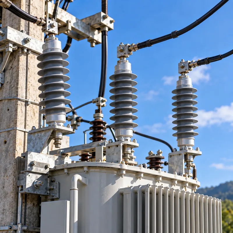
A modern metal-oxide arrester is a stack of zinc oxide varistor blocks inside a porcelain or polymer housing. Its current-voltage characteristic is extremely steep:
- At continuous operating voltage, leakage current is around a milliampere, mostly capacitive.
- At the reference voltage, around the rated voltage Ur, current reaches a few milliamperes resistive.
- During a 10 kA lightning surge, voltage rises only to the residual voltage, typically about 2.5–3.5 times the peak of Uc depending on design.
Because there are no series gaps, the arrester responds in nanoseconds and stops conducting as soon as the surge passes, without the power-follow current that gapped designs had to interrupt.
A surge arrester is not a lightning rod. Air terminals and shield wires intercept direct strikes to structures and lines; arresters limit the voltage that reaches equipment insulation from strikes and switching events. Both are part of insulation coordination under IEC 60071-1 and IEC 60071-2, along with the equipment's basic insulation level. For the insulation side of that balance, see our transformer insulation engineering guide.
Surge Arrester Ratings Explained
High voltage arrester data sheets list many values. These are the ones that drive selection.
| Rating | IEC term | IEEE term | What it means |
|---|---|---|---|
| Continuous operating voltage | Uc | MCOV | Maximum RMS voltage that may be applied continuously between terminals |
| Rated voltage | Ur | Duty-cycle voltage | RMS voltage the arrester withstands for 10 s in the operating duty test; usually about 1.25 × Uc |
| Nominal discharge current | In | Classifying current | Peak 8/20 µs current used to classify the arrester: 2.5, 5, 10 or 20 kA |
| Lightning impulse protective level | Upl | Discharge voltage | Maximum residual voltage at In |
| Switching impulse protective level | Ups | Switching surge protective level | Residual voltage at a specified switching current |
| Energy or charge capability | Wth, Qrs | Energy rating | Thermal energy or charge the arrester absorbs without thermal runaway |
| Temporary overvoltage capability | TOV curve | TOV curve | How long the arrester tolerates power-frequency overvoltage above Uc |
| Short-circuit rating | Is | Pressure relief | Fault current the housing withstands without violent shattering if the arrester fails |
IEC 60099-4:2014 groups arresters into classes: SH, SM and SL for station use (20, 10 and 10 kA In) and DH, DM and DL for distribution (10, 5 and 2.5 kA In). IEEE C62.11 uses station and distribution classes with heavy, normal and light duty distribution variants. Higher classes have greater energy capability and lower residual voltages per kV of Uc.
How to Select a Surge Arrester Step by Step
Selection follows a sequence set out in IEC 60099-5 and IEEE C62.22.
- Find the highest system voltage Um and the grounding method. For an 11 kV system, Um = 12 kV.
- Set Uc from grounding. Solidly earthed:
Uc ≥ 1.05 × Um / √3. Isolated or resonant earthed with sustained earth faults:Uc ≥ Um, because healthy phases rise to line voltage during a fault. Resistance-grounded with fast clearing: check TOV capability against the earth fault factor and clearing time. - Check temporary overvoltage from load rejection or ferroresonance against the arrester's TOV curve.
- Choose the class by expected lightning and switching duty: distribution class for pole-mounted and pad-mounted transformers, station class for substations, line arresters and capacitor banks.
- Calculate protective margin at the protected equipment, including lead length and separation distance.
- Select housing and creepage for site pollution per IEC TS 60815, and short-circuit rating at least equal to the earth fault current.
- Specify mounting: on the transformer tank, on a crossarm, as an elbow arrester for separable connectors, or inside switchgear.
Grounding is the most common source of error. A neutral earthing resistor or resonant coil changes the voltage on healthy phases during an earth fault, which our neutral earthing resistor guide explains. If grounding is uncertain, choose Uc for the worse case and accept a slightly higher residual voltage.
Worked Example: Protective Margin for a Transformer Lightning Arrester
An 11 kV, solidly earthed overhead feeder supplies a pole-mounted transformer with HV BIL of 75 kV.
Step 1, Uc: Uc ≥ 1.05 × 12 / 1.732 = 7.3 kV. Choose the next standard distribution-class arrester above this, with an illustrative data sheet residual voltage of 32 kV at 10 kA, 8/20 µs.
Step 2, lead voltage: connecting leads have inductance of roughly 1 µH per meter. A lightning current front of 10 kA/µs gives V = L × di/dt = 1 µH/m × 10 kA/µs = 10 kV per meter. With 1.0 m of total lead (line lead plus ground lead), add 10 kV.
Step 3, separation distance: if the arrester is a distance d from the transformer bushing, traveling-wave reflection adds approximately ΔV = 2 × S × d / v, where S is surge steepness and v is about 300 m/µs. With S = 500 kV/µs and d = 3 m: ΔV = 2 × 500 × 3 / 300 = 10 kV.
Step 4, margin: voltage at the bushing ≈ 32 + 10 + 10 = 52 kV. Protective ratio PR = BIL / V = 75 / 52 = 1.44, a 44% margin, above the IEEE C62.22 minimum of 20%.
Same arrester, poor installation: with 3 m of leads and 6 m separation, V ≈ 32 + 30 + 20 = 82 kV and PR = 0.91, so the transformer is not protected. This is why arresters for transformers are mounted directly on the tank or bushing bracket, with the ground lead bonded to the tank. If the system were isolated-neutral, Uc would rise to about 12 kV and residual voltage to perhaps 45–50 kV, leaving much less margin; there the short-lead installation becomes essential.
Where to Install Surge Arresters: Transformers and Substations
Arrester location matters as much as rating. Typical locations are:
- Pole-mounted transformers: one arrester per HV phase on the tank or crossarm, connected before the fuse cutout or on the transformer side depending on utility practice. See our 3 phase pole-mounted transformer guide.
- Riser poles: at every overhead-to-underground transition, protecting the cable and the equipment at its far end.
- Pad-mounted transformers: elbow arresters on separable connectors, especially at the open point of a loop, where reflected surges double.
- Substation line entrances: station-class arresters on each incoming overhead line.
- Power transformer terminals: on the HV side, and on the LV side where it connects to overhead lines or where transferred surges are a concern.
- Inside switchgear: on cable feeders to motors or capacitor banks, and where vacuum breakers switch inductive loads, sometimes alongside RC snubbers.
- Cable terminations of long cables, at both ends where surges can enter from either side.
| Location | Typical class | Main concern |
|---|---|---|
| Distribution transformer HV | DH or DM / distribution heavy or normal duty | Lightning on overhead line |
| Cable riser pole | DH / heavy duty or riser pole type | Reflection at open cable end |
| Substation line entrance | SM or SH / station class | Lightning and switching surges |
| Capacitor bank | Station class, high energy | Switching energy, restrike |
| MV motor feeder in switchgear | DM or SL | Switching transients |
A surge arrester in a substation forms part of the overall protection scheme described in our substation protection engineering guide.
Ground Arrester Connections and Earthing
An arrester can only divert current if it has a low-impedance path to earth. The ground connection is therefore part of the arrester, and the phrase "ground arrester" in practice usually refers to this earthing side of the installation.
- Bond to the protected equipment. Connect the arrester ground terminal directly to the transformer tank or switchgear earth bar, then to the station or pole ground. This keeps the voltage between the arrester ground and the equipment frame small.
- Keep it short and straight. Every meter of conductor adds about 10 kV under a steep surge, as the worked example shows; avoid sharp bends.
- Low earth resistance. Utilities commonly target values such as 10 Ω or lower for distribution transformer grounds, and much lower for substations, where the ground grid is designed to IEEE 80 for touch and step voltages; see our grounding grid substation design guide.
- Ground lead disconnector. Distribution arresters often include a device that separates the ground lead if the arrester fails, removing the fault and giving a visible indication.
- Interconnect HV and LV grounds where local practice permits, to limit potential rise between transformer windings during surges; follow the utility's rules on common or separate earthing.
For transformer neutral and frame earthing methods in general, read our transformer grounding system guide.
Surge Arrester vs Low-Voltage SPD
Low-voltage surge protective devices (SPDs) are built on similar metal-oxide varistor or spark-gap technology but follow different standards and ratings.
| Feature | MV/HV surge arrester | LV surge protective device |
|---|---|---|
| Standards | IEC 60099-4, IEEE C62.11 | IEC 61643-11, UL 1449 |
| Voltage range | Above 1 kV to over 800 kV systems | Up to 1,000 V AC |
| Classification | Station and distribution classes, In 2.5–20 kA | IEC Type 1, 2, 3 (Iimp, In); UL Type 1–4 |
| Key voltage rating | Uc / MCOV, Ur | Uc, voltage protection level Up |
| Typical location | Transformer HV terminals, line entrances, cable ends | Service entrance, distribution boards, equipment |
| Backup protection | Ground lead disconnector, system protection | Dedicated fuse or breaker per manufacturer |
An MV arrester protects the transformer, but it does not protect LV equipment from surges transferred through the transformer or entering on LV lines. A coordinated scheme uses MV arresters on the HV side and a Type 1 or Type 2 SPD at the main LV switchboard, with further Type 2 or 3 devices near sensitive loads. For how these voltage classes are defined, see our LV, MV, HV and EHV voltage ranges article.
Next Steps: Specifying Arresters with Transformers and Substations
MARS supplies pole-mounted, pad-mounted, oil-immersed and dry-type transformers, compact substations and MV switchgear. Arresters are usually specified as part of these packages, so include their requirements in the main equipment RFQ.
- System nominal voltage, Um, frequency and grounding method, including earth fault clearing time.
- Equipment BIL and required protective margin.
- Arrester class (IEC 60099-4 or IEEE C62.11) and nominal discharge current.
- Mounting: on tank, on bracket, elbow type for separable connectors, or inside switchgear cable compartments.
- Housing type (polymer or porcelain), creepage per site pollution level and altitude.
- LV SPD requirements at the main switchboard.
Ask for arrester data sheets with residual voltages at several discharge currents, TOV curves and energy ratings, and for the transformer BIL in the same submittal, so the protective margin can be checked before manufacture. Where arresters are factory-mounted on the transformer, confirm lead lengths and the ground connection to the tank on the general arrangement drawing.
Explore our transformer substations and pole-mounted transformers, then request a quote. Typical lead time for distribution transformers and switchgear is 25–45 days.
Frequently asked questions
What is the difference between a lightning arrester and a surge arrester?
Today the terms mean the same device. Historically, lightning arresters used series spark gaps with silicon-carbide blocks and were mainly for lightning. Modern gapless metal-oxide surge arresters protect against both lightning and switching surges, respond faster and have no power-follow current.
Why is a surge arrester installed on a transformer?
Transformer windings are vulnerable to lightning and switching surges that exceed their basic insulation level. An arrester mounted at the transformer terminals clamps the voltage to its residual level, keeping the stress below BIL with margin. Mounting it directly on the tank minimizes lead length and separation voltage.
How do I choose MCOV for a surge arrester?
On solidly grounded systems, choose MCOV or Uc at least about 1.05 times the maximum line-to-ground voltage, Um/√3. On ungrounded, high-resistance or resonant grounded systems, choose MCOV at least equal to the maximum line-to-line voltage, because healthy phases rise to that level during an earth fault.
What is the protective margin of a surge arrester?
Protective margin compares equipment insulation strength with the surge voltage at its terminals. For lightning, divide BIL by the arrester residual voltage plus lead and separation effects. IEEE C62.22 recommends a ratio of at least 1.2, a 20 percent margin, and IEC 60071-2 uses similar safety factors.
Where should surge arresters be located in a substation?
Install station-class arresters at each overhead line entrance and at the terminals of power transformers, as close as practical to the bushings. Add arresters at cable terminations, capacitor banks and motor feeders where switching surges or reflections are expected.
How do you know if a surge arrester has failed?
Signs include an operated ground lead disconnector, a cracked or tracked housing, or high resistive leakage current measured with a leakage current monitor. Thermal imaging may show a hot arrester. Failed arresters should be replaced promptly, because the protected equipment is exposed until they are.
Written and reviewed by the MARS application engineering team in Shanghai, who specify and test transformers, switchgear, substations and battery storage for projects in 40+ countries. Last updated .
Tags: surge arrester lightning surge arrester transformer lightning arrester surge arrester in substation high voltage surge arrester