Key takeaways
- NER resistance is line-to-neutral voltage divided by the chosen fault current, so 11 kV limited to 400 A needs about 15.9 Ω.
- Low-resistance grounding typically limits earth faults to 100–1,000 A for 10 s, while high-resistance grounding limits them to about 10 A or less continuously.
- For high-resistance grounding, resistor current should be at least equal to the system's total charging current, 3I_C0, to limit transient overvoltages.
- IEEE C57.32 defines neutral grounding device ratings, including time ratings of 10 s, 60 s, 10 minutes, extended time and continuous.
- A 400 A, 15.9 Ω resistor dissipates about 2.5 MW during a fault, absorbing roughly 25 MJ over a 10 s rating.
Quick answer: A neutral earthing resistor (NER), also called a neutral grounding resistor (NGR), is a resistor connected between a transformer or generator neutral and earth to limit earth fault current. Its resistance is R = V_LN / I_limit; for an 11 kV system limited to 400 A, R is about 15.9 Ω. NERs reduce fault damage and transient overvoltage while keeping faults detectable.
How a power system's neutral is connected to earth decides how large an earth fault current can be, how high the healthy phases rise during a fault, and whether protection can find the fault at all. Solid earthing gives very high fault current; an isolated neutral gives almost none but risks dangerous transient overvoltages. The neutral earthing resistor sits between these extremes and is the standard choice for many industrial, mining, generator and utility MV systems.
This guide is for protection engineers, substation designers and plant electrical managers. It explains the NGR meaning in electrical terms, compares grounding methods, gives sizing formulas with worked examples, covers the NGR of transformer connections and construction, and shows how the resistor interacts with protection and monitoring.
What Is a Neutral Earthing Resistor?
A neutral earthing resistor is a power resistor connected between the star point of a transformer or generator and the earthing system, sized to limit the current that flows during a phase-to-earth fault to a chosen value. In North American usage it is called a neutral grounding resistor (NGR); in IEC markets NER is more common. Both refer to the same device, and "grounding resistor" alone is often used in specifications.
During normal balanced operation, the neutral is at or near earth potential and the resistor carries almost no current. When one phase faults to earth, the fault loop is closed through the earth, the resistor and the transformer winding. Because the resistor is much larger than the other loop impedances, it sets the fault current almost entirely:
I_f ≈ V_LN / R_N, where V_LN = V_LL / √3.
The NGR meaning in electrical drawings is usually shown with a resistor symbol between the neutral bushing and the earth symbol, with a neutral current transformer and sometimes a disconnect switch. Most earth faults start as phase-to-earth faults, often cited as the large majority of all faults on cable and industrial systems, so controlling them shapes the whole protection scheme. The resistor keeps current low enough to limit burning and mechanical damage at the fault point, but high enough for protective relays to detect and clear the fault selectively. On solidly earthed systems, by comparison, earth fault current can approach or exceed three-phase fault current; see our fault current calculation guide.
Why Use a Neutral Grounding Resistor? Grounding Methods Compared
Each grounding method trades fault current against overvoltage and service continuity.
| Method | Earth fault current | Overvoltage on healthy phases | Typical use |
|---|---|---|---|
| Solidly grounded | Very high, similar to three-phase fault | Low, about 1.0–1.4 pu | LV systems, HV transmission, 4-wire MV distribution |
| Low-resistance grounded | 100–1,000 A typical | Up to about 1.73 pu, short duration | Industrial and utility MV, 3.3–33 kV |
| High-resistance grounded | About 1–10 A | 1.73 pu, transient limited to about 2.5 pu | 480–600 V industrial, generators, some 4.16 kV |
| Reactance grounded | Limited, often 25–100% of three-phase | Moderate | Generator neutrals, some utilities |
| Resonant (Petersen coil) | Very low, residual only | 1.73 pu sustained | Overhead MV networks in parts of Europe and Asia |
| Ungrounded | Capacitive charging only | 1.73 pu, risk of 5–6 pu with intermittent arcing | Legacy industrial systems |
Resistance grounding solves the main weaknesses of the extremes. Compared with solid grounding, it reduces damage to motor and generator cores, cuts the flash hazard of arcing earth faults and lowers step and touch voltages. Compared with ungrounded systems, it damps the escalating overvoltages caused by intermittent arcing faults, which can reach several times normal voltage and fail insulation elsewhere. IEEE 142 (the Green Book) and IEEE C62.92 series give the detailed application guidance. For the theory of system neutrals and their relation to earth voltage, see our article on neutral to ground voltage.
Low-Resistance vs High-Resistance Grounding
The two resistance grounding families behave very differently, and the choice drives relay design and operating practice.
| Feature | Low-resistance grounding (LRG) | High-resistance grounding (HRG) |
|---|---|---|
| Fault current | Typically 100–1,000 A, often 200–400 A | Typically 1–10 A |
| Time rating | 10 s common | Continuous or extended time |
| Action on fault | Trip faulted feeder quickly | Alarm; operation may continue while fault is located |
| Voltage range | MV, 2.4–35 kV | LV 480–1,000 V and MV up to about 5 kV; generators at higher voltages |
| Line-to-neutral loads | Permitted with suitable design | Not permitted (NEC 250.36 for 480–1,000 V systems) |
| Design criterion | Relay sensitivity and equipment damage | Resistor current at least system charging current 3I_C0 |
| Main benefit | Limits damage while allowing selective tripping | Service continuity on first fault |
HRG is popular in continuous process plants, because a single earth fault does not trip production; maintenance staff locate it with pulsing equipment and clear it at a convenient time. The risk is a second fault on another phase, which becomes a phase-to-phase fault, so NEC 250.36 requires ground detectors and qualified maintenance supervision. HRG is impractical at higher MV levels because system charging current grows with voltage and cable length, pushing the required resistor current above 10 A, where a sustained arcing fault starts causing serious damage. Underground mining rules in several countries limit earth fault current to 25 A or less for portable equipment, another specialized use of resistance grounding covered in our mining substation engineering guide.
How to Size a Neutral Earthing Resistor: Worked Examples
Sizing involves resistance, current, time rating and voltage.
Example 1: Low-resistance NER on an 11 kV transformer
- Choose fault current. The plant's feeder earth fault relays must detect faults reliably, and motor stator cores should be protected. A common choice is 400 A, well below the transformer's three-phase fault current but large enough for sensitive relaying.
- Calculate resistance:
R = V_LN / I = (11,000 / 1.732) / 400 = 6,351 / 400 = 15.9 Ω. - Power during fault:
P = I² × R = 400² × 15.9 = 2.54 MW. - Energy for a 10 s rating:
E = 2.54 MW × 10 s = 25.4 MJ. As a rough adiabatic check, stainless steel elements with specific heat about 0.5 kJ/kg·K and an allowed rise of 600 K need about25.4 × 10⁶ / (500 × 600) ≈ 85 kgof active element mass. - Voltage rating: the resistor and its insulation must withstand full line-to-neutral voltage, 6.35 kV, during the fault.
Example 2: High-resistance grounding at 480 V
- Determine charging current. Measured or calculated system charging current 3I_C0 = 1.5 A.
- Choose resistor current above it, for example 5 A.
- Calculate resistance:
R = 277 / 5 = 55.4 Ω. - Continuous power:
P = 5² × 55.4 = 1.39 kW, rated continuous because the system may run with a fault present.
The total fault current in the HRG case is the vector sum of resistive and capacitive parts, √(5² + 1.5²) = 5.2 A, still low enough to avoid significant arc damage.
NGR of Transformer: Connection and Grounding Transformers
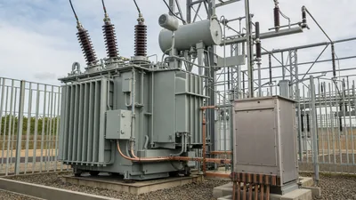
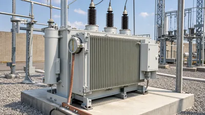
The NGR of a transformer is connected to the neutral point of a wye (star) winding. A neutral grounding resistor for a transformer therefore depends on the transformer having an accessible, adequately insulated neutral.
- Neutral bushing: the transformer must have a neutral bushing rated for the voltage that appears across the resistor, up to full line-to-neutral voltage during a fault. Specify this when ordering the transformer, because a graded or reduced neutral insulation level may not be suitable.
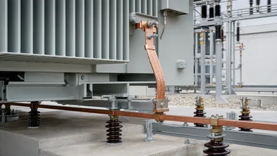
- Neutral conductor: cable or busbar from the neutral bushing to the NER, insulated for line-to-neutral voltage and rated for fault current over the time rating.
- Neutral CT: on the earth side of the resistor or in the neutral lead, supplying the earth fault relay (51N or 51G).
- Isolating switch: optional, to disconnect the resistor for maintenance; it must not be opened with the system running unless an alternative ground is present.
When the supply winding is delta, as in many Dyn and YNd arrangements on the MV side, there is no neutral to connect to. A grounding (earthing) transformer, usually zigzag or wye-delta, creates an artificial neutral, and the NER connects to its neutral. Its rating is matched to the NER current and time rating, not to load. Our earthing transformer engineering guide and grounding transformer engineering guide cover the sizing.
With multiple transformers in parallel, decide whether each has its own NER or whether a single resistor serves the bus. Otherwise the earth fault current can double when two transformers are paralleled, upsetting relay settings.
Components, Construction and Time Ratings
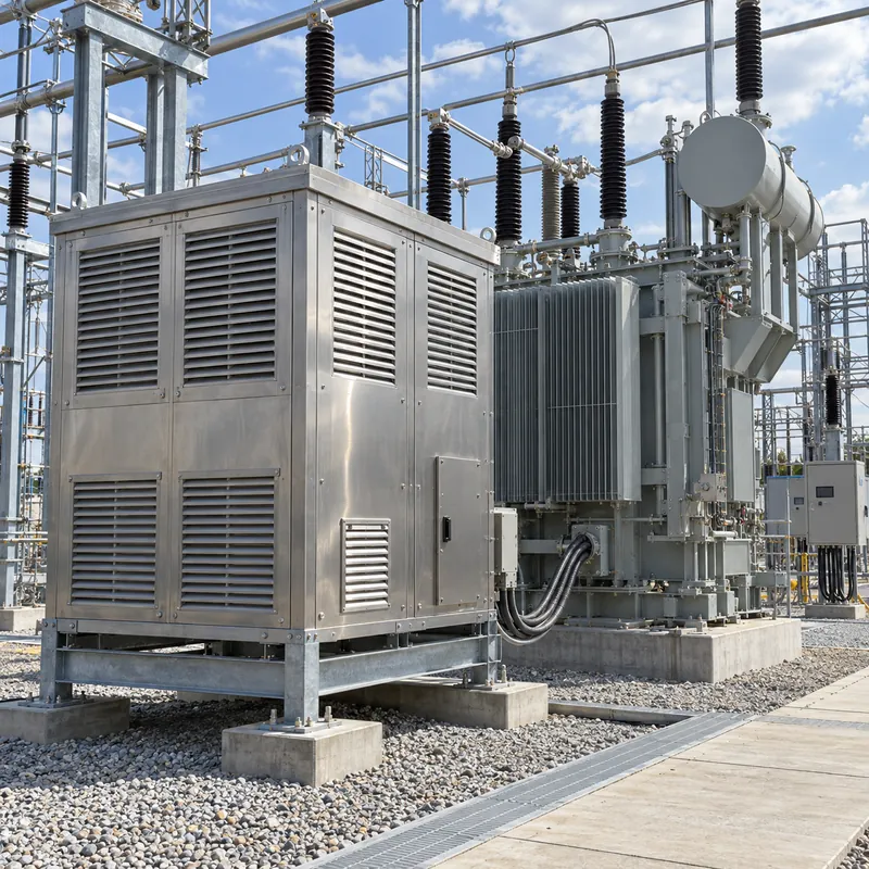
A typical neutral earthing resistor package includes:
- Resistor elements: stainless steel grids, edge-wound ribbon or wire elements, selected for stable resistance with temperature. Stainless steel alloys keep resistance change modest across the temperature rise.
- Insulators supporting the element stack, rated for the system's line-to-neutral voltage and impulse level.
- Enclosure: galvanized or stainless steel, usually ventilated (for example IP23) for outdoor use, with screened openings and a roof to shed rain.
- Entry bushing or cable box for the neutral conductor, and an earth terminal.
- Accessories: neutral CT, disconnect switch, NER monitoring relay, space heaters where condensation is likely.
IEEE C57.32 defines time ratings, each with its own permissible temperature rise:
| Time rating | Typical application |
|---|---|
| 10 s | LRG with fast-tripping feeder protection |
| 60 s | LRG where backup protection or reclosing extends fault duration |
| 10 minutes | Systems with slow fault clearing, some generators |
| Extended time | Faults allowed to persist for longer periods, limited annual duty |
| Continuous | HRG systems that may operate with a fault present |
Specify the time rating to cover the slowest credible clearing time, including backup protection, not just primary relay time. Factory tests normally include resistance measurement and a dielectric test of the insulation to the enclosure.
Protection and Monitoring with a Neutral Earthing Resistor
Resistance grounding works only if protection and monitoring are set to match it.
- Earth fault relay sensitivity: the relay pickup sets how much of the transformer winding is protected. Faults near the neutral produce less current, because driving voltage falls in proportion to the distance from the neutral. With a 400 A NER and a 40 A pickup, faults in the last
40 / 400 = 10%of the winding near the neutral are not detected, so about 90% of the winding is covered. - Grading: feeder earth fault relays trip first, the neutral relay acts as backup, and its time must stay within the NER time rating.
- Restricted earth fault protection (64REF): a differential scheme using the neutral CT and phase CTs, giving sensitive, fast protection of the transformer winding itself; see our transformer relay protection guide.
- NER monitoring: an open-circuited resistor silently converts the system to ungrounded; a shorted resistor converts it to solidly grounded. An NGR monitor continuously measures resistor continuity and alarms on either condition. It is strongly recommended for HRG and mining systems and increasingly specified for LRG.
- Arrester selection: the healthy phases rise toward line-to-line voltage during an earth fault, so surge arrester continuous voltage must account for it; see our surge arrester guide.
Periodically verify resistance against nameplate, inspect elements for corrosion or heat damage, and test the neutral CT and relay, typically during transformer outages.
Next Steps: Specifying NER Packages with Transformers and Substations
MARS supplies oil-immersed and dry-type transformers, power transformers up to 110 kV class and compact or containerised substations, where the neutral connection and earthing method must be agreed at design stage. Coordinating the transformer neutral, any grounding transformer and the NER in one RFQ avoids mismatched insulation and ratings.
Specify:
- System voltage, frequency and whether the neutral is from the main transformer or a grounding transformer.
- Earthing method (LRG or HRG), fault current limit and time rating per IEEE C57.32.
- Neutral bushing rating and neutral insulation level on the transformer.
- Ambient conditions, altitude, enclosure IP rating and mounting (ground or transformer-mounted).
- Neutral CT ratio and class, disconnect switch, NER monitor and SCADA alarms.
- Test requirements and documentation.
Ask for resistance tolerance, temperature coefficient and the calculated temperature rise at the time rating in the NER data sheet, and confirm that the transformer neutral bushing, neutral cable and grounding transformer, if any, carry the same current and time rating as the resistor.
Explore our transformer substations and oil-immersed transformers, then request a quote with your single-line diagram and grounding philosophy.
Frequently asked questions
What is the purpose of a neutral earthing resistor?
A neutral earthing resistor limits the current that flows during a phase-to-earth fault, reducing damage at the fault, arc flash energy and mechanical stress on equipment. It also prevents the dangerous transient overvoltages of ungrounded systems while keeping fault current high enough for relays to detect and clear the fault.
How do you calculate the resistance of a neutral grounding resistor?
Divide line-to-neutral voltage by the desired earth fault current: R = (V_LL / √3) / I. For an 11 kV system limited to 400 A, R = 6,351 / 400 = 15.9 Ω. For a 480 V high-resistance system limited to 5 A, R = 277 / 5 = 55.4 Ω.
What does NGR mean in electrical systems?
NGR stands for neutral grounding resistor, the North American name for a neutral earthing resistor. It is connected between the neutral of a transformer or generator and ground to limit earth fault current. Specifications often abbreviate it as NGR, and single-line diagrams show it below the neutral connection.
What is the difference between low and high resistance grounding?
Low-resistance grounding limits earth faults to about 100–1,000 A and trips the faulted circuit within seconds. High-resistance grounding limits faults to about 10 A or less and usually only alarms, so the system can keep running while the fault is located. HRG requires the resistor current to exceed system charging current.
Can a neutral grounding resistor be used with a delta transformer?
Not directly, because a delta winding has no neutral point. A grounding transformer, typically zigzag or wye-delta, is connected to the system to create an artificial neutral, and the resistor is connected between that neutral and earth. The grounding transformer is sized for the resistor's current and time rating.
What happens if a neutral grounding resistor fails open?
An open resistor turns the system into an ungrounded system. Earth faults are no longer limited and detected as designed, and intermittent arcing faults can create high transient overvoltages. An NGR monitor that continuously checks resistor continuity and alarms on open or short conditions is the usual safeguard.
Written and reviewed by the MARS application engineering team in Shanghai, who specify and test transformers, switchgear, substations and battery storage for projects in 40+ countries. Last updated .
Tags: neutral earthing resistor neutral grounding resistor ngr of transformer neutral grounding resistor for transformer grounding resistor