Key takeaways
- A mining substation steps down high or medium distribution voltages (typically 3.3 kV to 33 kV) to utilisation levels (400 V to 1100 V) using rugged, mobile skid or container platforms.
- Underground substations require dry-type cast-resin or VPI transformers because oil-immersed units introduce severe fire and toxic vapour hazards in restricted drift spaces.
- Neutral Grounding Resistors (NGR) combined with earth-leakage relays limit phase-to-ground fault current to 5 A or 10 A to prevent hazardous touch potentials and reduce arc-flash energy.
- Feeders feeding underground equipment require continuous earth-continuity monitoring through an integrated pilot core to trip supply breakers if the ground return path is broken.
- Mine duty enclosures must comply with structural rigidity tests for dragging and winching, offering IP55 to IP66 ingress protection and internal arc classification under IEC 62271-200.
Quick answer: A mining substation is a specialised electrical power centre designed to step down distribution voltages (3.3 kV to 33 kV) to utilisation voltages (400 V to 1100 V) in arduous surface and subterranean mining environments. Engineered on heavy structural skids or transportable enclosures, these substations combine dry-type transformers, arc-resistant switchgear, and earth-fault limitation schemes to deliver power to mobile drills, continuous miners, pumps, and conveyors.
Mining environments impose electrical and mechanical stresses rarely encountered in standard utility or industrial installations. Substation equipment must withstand severe mechanical shocks from blasting, routine towing across uneven floor strata, corrosive pit water, and heavy atmospheric dust. In underground tunnels, space restrictions and ventilation limits strictly dictate thermal footprints and eliminate the use of volatile, flammable dielectric fluids. Whether mounted on an open-pit bench or parked within an underground excavation drift, specifying a mining transformer substation requires rigorous balance among short-circuit resilience, compact geometry, personnel safety, and regulatory compliance under standards such as IEC 62271-200, AS/NZS 4871, and MSHA 30 CFR 75.
Architecture of an Underground Mining Substation
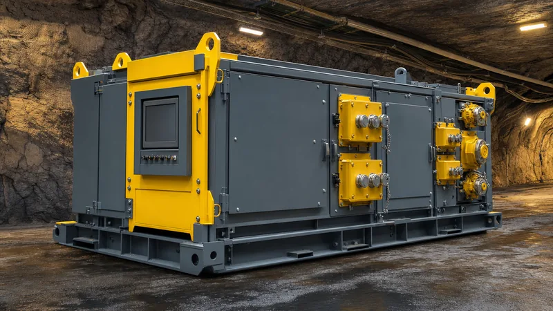
An underground mining substation integrates incoming medium-voltage (MV) isolation, thermal transformation, low-voltage (LV) protection, and outgoing feeder control into a unified, low-profile mechanical skid. Standard industrial units cannot navigate the narrow cage shafts, declining drifts, and tight turning radii of hard-rock or soft-rock underground operations.
The MV primary stage receives incoming power—typically between 6.6 kV and 22 kV—via flexible, armoured mining cables terminated in certified coupler plugs or bolt-on cable boxes. Primary isolation is handled by vacuum load-break switches or compact vacuum circuit breakers housed in arc-resistant enclosures. Upstream circuit protection incorporates self-powered numerical protection relays providing overcurrent (ANSI 50/51), earth fault (ANSI 50N/51N), and under-voltage monitoring.
The transformation section drops primary distribution lines to secondary utilisation levels, predominantly 1000 V or 1100 V for continuous mining machinery, longwall shearers, and jumbo drills, or 400 V to 690 V for auxiliary ventilation fans and dewatering pumps. Because subterranean fires represent catastrophic safety risks, oil-filled designs are prohibited or strictly governed by rigid firebreak rules. Engineers deploy Class H or Class C insulated dry-type transformers—either vacuum pressure impregnated (VPI) or cast-resin encapsulated—complying with IEC 60076-11 fire behaviour class F1.
The LV distribution section distributes power across multiple outgoing circuits, detailed further in our guide to underground mining electrical equipment. Each outgoing feeder incorporates an individual contactor or moulded-case circuit breaker (MCCB), an earth-fault current transformer, and pilot wire monitoring systems to cut supply instantaneously if equipment trailing cables sustain damage.
Surface Mining Substation vs Underground Substation
Selecting between an open-cast surface mining substation and an underground substation involves fundamentally different environmental profiles, fire ratings, footprint limits, and mobility parameters.
Surface mine electrical distribution centres operate in open pits, rail-loading yards, and processing facilities. These systems frequently leverage modular prefabricated e-houses or structural trailer units that can incorporate liquid-cooled or mineral-oil-filled power transformers compliant with IEC 60076-2, provided appropriate containment bunds are established. In contrast, an underground electrical substation operates in confined cross-cuts and dead-end headings where airflow is supplied via forced ventilation ducts, making toxic off-gassing and heat load generation critical design factors.
| Engineering Parameter | Surface Mining Substation | Underground Electrical Substation |
|---|---|---|
| Enclosure Profile | Modular e-house, ISO container, or multi-axle trailer | Low-clearance heavy structural steel skid with sled runners |
| Transformer Dielectric | Mineral oil, synthetic ester, or VPI dry-type | Cast resin (certified fire-rated) or high-grade silicone VPI only |
| Standard Voltages | Primary: 11 kV–66 kV; Secondary: 3.3 kV–11 kV | Primary: 3.3 kV–22 kV; Secondary: 400 V, 1000 V, 1100 V |
| Ingress Protection (IP) | IP55 to IP65 with sun-shields and HVAC | IP55 to IP66; water-jet and slurry wash-down rated |
| Arc Flash Containment | IAC AFLR per IEC 62271-200, venting upwards | IAC AFLR with ducting, arc deflectors, or optical quenching |
| Relocation Method | Crane lifts, prime mover tractor, or flatbed float | Direct winching, tractor towing, or load-haul-dump (LHD) push |
| Earthing Scheme | Solidly grounded or low-resistance grounded (NER) | Resistance grounded (NGR) strictly limited to 5 A or 10 A |
Earthing and Protection Schemes for a Mine Electrical Substation
Earthing architectures within a mine electrical substation prioritise life-safety by preventing lethal frame touch voltages when insulation fails on mobile equipment fed through long trailing cables.
Underground reticulation systems forbid solidly grounded neutrals. Instead, the secondary neutral point of the substation transformer is grounded through a continuous-duty Neutral Grounding Resistor (NGR). Governed by standards such as AS/NZS 4871.1 and MSHA Title 30 CFR Section 75.800, the NGR limits phase-to-earth fault currents to low values—typically 5 A or 10 A on 1000 V networks. This current limitation serves two critical functions: it clamps potential rises on machine chassis to below 25 V or 50 V under fault conditions, and it curtails thermal energy to prevent ignition in coal or gassy hard-rock environments.
To guarantee protection reliability, the mining substation incorporates specialised instrumentation:
- Restricted Earth Fault (REF) and Core-Balance CTs: High-sensitivity toroidal current transformers detect zero-sequence leakage currents as low as 100 mA, triggering sub-second breaker trips via selective substation protection schemes.
- Earth Continuity Pilot Monitors: A low-voltage DC or high-frequency pilot circuit travels through a dedicated core in the trailing cable to the mobile plant chassis and returns via the ground conductors. If the ground conductor breaks, resistance shifts, or the cable uncouples, the monitor drops the control circuit and trips the feeder breaker.
- NGR Monitoring Relays: Dedicated monitors continuously verify the health of the neutral grounding resistor. An open-circuit NGR leaves the system ungrounded, causing undetected overvoltages, while a short-circuit NGR defeats current limitation. Detection of either condition trips the primary MV supply breaker immediately.
- Optical Arc Detection: Photodiode optical sensors positioned across busbar compartments detect the light flash of an arc within 1 to 2 milliseconds, tripping the incomer long before pressure relief flaps open, minimising arc flash hazards to operating personnel.
Sizing an Underground Mine Electrical Substation: Worked Calculation
Sizing an underground mine electrical substation requires calculating both continuous thermal load capacity and dynamic voltage stability during across-the-line starting of heavy induction motors.
Consider an underground production heading operating at 1000 V, 3-phase, 50 Hz. The skid substation feeds three primary dynamic loads simultaneously: one electric jumbo drill (160 kW, operating $\cos\phi = 0.85$, starting current $I_{start} = 6 \times I_n$), one main mine dewatering pump (110 kW, $\cos\phi = 0.88$), and two auxiliary ventilation fans (each 55 kW, $\cos\phi = 0.86$). The system has an aggregate motor efficiency ($\\eta$) of 93%.
- Calculate Total Running Active Power ($P_{total}$):
$$P_{total} = \frac{160 + 110 + (2 \times 55)}{0.93} = \frac{380}{0.93} = 408.6\text{ kW}$$ - Determine System Reactive Power ($Q_{total}$) and Apparent Power ($S_{load}$):
Average loaded power factor is approximately $\cos\phi = 0.86$ (where $\tan\phi = 0.593$).
$$Q_{total} = P_{total} \times \tan\phi = 408.6 \times 0.593 = 242.3\text{ kVAR}$$
$$S_{load} = \sqrt{P_{total}^2 + Q_{total}^2} = \sqrt{408.6^2 + 242.3^2} = 475.1\text{ kVA}$$ - Account for Production Diversity and Expansion:
Applying a 1.25 operational margin for transient shock loads, hydraulic duty cycles, and future auxiliary loads yields:
$$S_{target} = 475.1\text{ kVA} \times 1.25 = 593.9\text{ kVA}$$ - Verify Direct-on-Line (DOL) Motor Starting Voltage Drop:
The 160 kW jumbo drill is the largest machine, starting while all other equipment is fully energised. Its starting apparent power demand is:
$$S_{start} = \frac{160\text{ kW}}{0.93 \times 0.85} \times 6 = 1213.6\text{ kVA}\quad (\text{at }\cos\phi_{start} = 0.30)$$
To prevent contactors dropping out, standard mine criteria (such as IEEE 399) mandate that maximum bus voltage dip must not exceed 10% during motor start. If an engineer evaluated a standard 630 kVA transformer with impedance $Z_t = 5.0\%$, the total short-circuit capacity of the transformer ($S_{sc}$) is:
$$S_{sc} = \frac{630\text{ kVA}}{0.05} = 12600\text{ kVA}$$
The prospective percentage voltage dip on the LV busbar is estimated by:
$$\Delta V_{\%} \approx \frac{S_{start}}{S_{sc}} \times 100 = \frac{1213.6}{12600} \times 100 = 9.63\%$$
While 9.63% sits marginally below the 10% threshold, it leaves negligible margin for cable impedance across long runs. Therefore, a standard 800 kVA or 1000 kVA rating is selected. Sizing to an 800 kVA, 11 kV / 1.05 kV unit with $Z_t = 5.5\%$ drops $\Delta V_{\%}$ to 8.34%, ensuring stable operation and permitting long trailing cable distances. Further integration guidelines can be reviewed in our unit substation engineering guide.
Mechanical Design and Compliance for Underground Electrical Substation Units
A compliant underground mine substation must balance electrical isolation with extreme structural endurance, certified in accordance with regional mining directives such as MSHA, AS/NZS 4871.1, and EN 60079 series standards.
Physical structural integrity demands a heavy plate steel skid base—typically constructed from 250 mm to 300 mm universal beam sections equipped with reinforced pull rings and heavy-duty towing lugs. The underside features replaceable wear plates or hardened sled runners designed to be dragged over broken rock, ballast, and steep inclines up to 1:4 (14 degrees) without twisting internal bus structures. Lifting eyes are engineered with a minimum safety factor of 5:1 for vertical cage hoisting.
Underground environmental ratings demand dual consideration:
- Ingress Protection: External enclosures must achieve a minimum rating of IP55 to resist high-pressure water jets during drift washing and prevent the ingress of conductive ore dust. Gasket materials must be non-hygroscopic, flame-retardant neoprene or silicone.
- Cooling in Restricted Headings: Standard convection-cooled radiators struggle in blind drifts where air velocities drop below 0.5 m/s. Radiator banks must be protected behind heavy debris grilles while maintaining adequate surface area. Cast-resin transformers should feature embedded PT100 temperature sensors linked to digital winding temperature relays to initiate stepped load shedding before insulation degrades.
- Arc Containment and Deflection: Medium-voltage compartments must comply with IEC 62271-200 Internal Arc Classification (IAC). When used underground, switchgear cannot safely vent hot gases into the drift roof, where ventilation bag lines and communication cables reside. Instead, integrated arc deflector ducts or ceramic cooling filters cool and vent plasma toward designated discharge zones away from accessways.
Next steps: specifying and sourcing
Specifying a custom mining substation begins with a precise mechanical and electrical data sheet. When initiating technical inquiries, engineers should supply: primary supply voltage and basic impulse level (BIL), desired secondary utilization voltages, motor starting schedules, incoming/outgoing coupler models, enclosure dimensional boundaries (maximum height, width, and weight for shaft clearance), and regional mine compliance requirements (MSHA, AS/NZS, or IEC).
Our technical sales team manufactures fully certified mine-duty distribution substations, integrating factory-engineered transformer substations, compact HV/LV switchgear, and rugged cast-resin power units built for aggressive environments. Submit your mine layouts and load schedules via our substation quotation portal or reach out directly through our engineering contact page to discuss technical parameters with our application team.
Frequently asked questions
What is a mining substation?
A mining substation is an electrical assembly that transforms medium-voltage supply (3.3 kV to 33 kV) into lower utilisation voltages for mining machinery. It is built on a heavy structural skid or within a transportable enclosure to withstand harsh operating conditions, mechanical shocks, and dust.
Why are dry-type transformers used in an underground substation?
Dry-type transformers eliminate the risk of oil fires and toxic vapour release in confined, unventilated underground tunnels. Their cast-resin or VPI construction provides high moisture resistance and non-flammable operation conforming to strict underground fire safety standards.
What is the purpose of a neutral grounding resistor in a mine electrical substation?
A neutral grounding resistor (NGR) limits phase-to-ground fault current to a safe value, typically 5 A or 10 A. This prevents hazardous touch potentials on machine frames, limits arc flash energy, and protects personnel from lethal electrical shock.
How does an underground mine substation handle trailing cable faults?
It uses integrated pilot wire monitoring relays coupled with core-balance current transformers on each outgoing circuit. If the pilot loop breaks or ground-fault current exceeds predetermined thresholds (often 100 mA to 500 mA), the circuit breaker trips instantaneously.
What standard voltages are used by an underground electrical substation?
Common primary voltages range from 3.3 kV to 22 kV. Secondary utilisation voltages are typically 1000 V or 1100 V for production drills and shearers, and 400 V, 480 V, or 690 V for auxiliary ventilation fans, lighting, and dewatering pumps.
Tags: mining substation underground substation mine electrical substation underground mining substation underground electrical substation


