Key takeaways
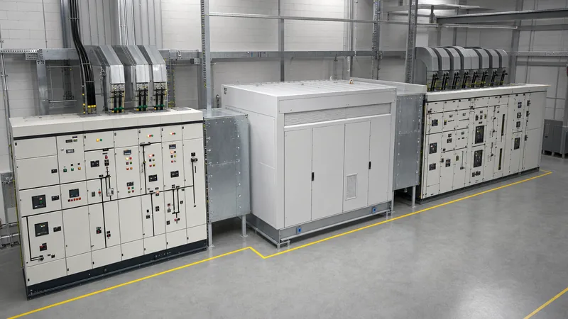
- A unit substation integrates medium-voltage switchgear, a step-down transformer, and low-voltage distribution switchgear into a factory-coordinated assembly governed by IEEE C37.121 and IEC 62271-202.
- Secondary unit substations step voltages down below 1 kV (typically 480 V, 400 V, or 208 V), whereas primary unit substations supply downstream distribution networks above 1 kV.
- Close-coupled throat or flange connections eliminate external cabling between the transformer and switchgear sections, reducing installation footprint and transmission impedance.
- Standard unit substation transformer selection hinges on winding thermal rise limits (55/65 deg C for oil, 80/115/150 deg C for dry-type) and short-circuit impedance matching to limit low-voltage busbar fault levels.
- Adequate fault level withstand calculations require evaluating both symmetrical interrupting capacity and asymmetrical peak dynamic bracing according to IEEE C37.20.1 and IEC 61439-2.
Quick answer: A unit substation is a factory-assembled, coordinated electrical power distribution centre comprising an incoming medium-voltage (MV) termination or switchgear section, a close-coupled unit substation transformer, and an outgoing low-voltage (LV) or secondary distribution switchgear line-up. It transfers power from distribution levels down to utilisation voltages within industrial plants, data centres, and commercial infrastructure.
Originating as an engineered alternative to field-erected, open-structure substations, the modern unit substation consolidates three distinct electrical subsystems into a single mechanical and electrical envelope. By co-locating primary switching, voltage transformation, and secondary circuit protection, industrial facilities minimise structural civil works, reduce field-run cable tray overhead, and improve reliability under severe short-circuit conditions. Standards such as IEEE C37.121 and IEC 62271-202 govern the mechanical tolerances, inter-compartment dielectric boundaries, and thermal performance of these assemblies.
Specifying an engineered unit substation requires careful alignment between electrical fault levels, environmental conditions, duty cycles, and protection schemes. Whether deploying indoor dry-type assemblies adjacent to critical data centre white space or outdoor liquid-filled packages in harsh industrial environments, engineers must evaluate system impedance, arc flash boundaries, and selective coordination to guarantee uninterrupted operations.
What is a Unit Substation and How Does It Work?
A unit substation functions by accepting primary distribution voltage, stepping it down through an integrated transformer, and distributing power across multiple feeder circuits via an integrated switchgear assembly. Rather than deploying standalone components connected by lengthy external power cables or elevated bus duct, the unit substation integrates the incoming high- or medium-voltage line-up directly to the primary transformer terminals using a transition flange or throat connection, with the secondary terminals similarly coupled directly to the low-voltage switchboard busbars.
The assembly comprises three core sections operating in unison:
- Primary incoming section: Houses the medium-voltage termination compartments, which may include load-break air switches, vacuum fault interrupters, or gas-insulated disconnectors. It provides isolation, primary overcurrent protection, and surge suppression. Detailed designs frequently incorporate metal-clad switchgear to provide compartmentalised safety barriers.
- Transformer section: Steps down the distribution voltage (commonly 4.16 kV up to 34.5 kV) to utilisation voltage (such as 480 V, 400 V, or 600 V). This unit substation transformer is mechanically engineered to couple directly to the adjacent switchgear enclosures, eliminating separate terminal boxes.
- Secondary outgoing section: Distributes the stepped-down energy through low-voltage power circuit breakers or moulded-case circuit breakers (MCCBs). This section contains metering, automated transfer switching, and protective relays configured for zone-selective interlocking.
Because these three sections share a continuous ground bus and matched dynamic short-circuit bracing, the entire line-up withstands transient mechanical stresses caused by through-faults without risking displacement of internal interconnections.
Types of Unit Substations: Primary vs Secondary Configurations
Unit substations are categorised primarily by their secondary output voltage into primary unit substations and secondary unit substations. Understanding the distinction is essential for facility planning, utility interconnection compliance, and fault-clearing design.
A primary unit substation accepts transmission or sub-transmission voltages (typically 34.5 kV to 138 kV) and steps them down to medium-voltage distribution levels between 2.4 kV and 34.5 kV. The secondary section consists of medium-voltage switchgear—such as metal-clad vacuum breaker gear—which feeds regional distribution loops, large medium-voltage motors, or downstream secondary substations across a broad campus. These installations generally serve utility substations, mining complexes, and large-scale manufacturing facilities.
Conversely, a secondary unit substation receives medium-voltage power (typically 2.4 kV to 34.5 kV) and steps it down directly to low-voltage utilisation levels below 1,000 V (most commonly 480 V three-phase 3-wire, 480Y/277 V, or 400Y/230 V 4-wire). The secondary switchgear consists of low-voltage metal-enclosed switchgear complying with IEEE C37.20.1 or IEC 61439-2. These units represent the workhorses of industrial power distribution, placed within plant switchrooms or on factory production floors right at the load centre to eliminate resistive low-voltage line losses.
Engineers also classify configurations by system layout:
- Radial substation: Utilises a single incoming primary feed and a single transformer to serve the secondary bus. It offers the lowest capital cost but provides zero redundancy during transformer or primary switch servicing.
- Secondary-selective substation: Employs two independent incoming primary circuits and two transformers feeding two halves of a split low-voltage bus, connected through a normally open tie circuit breaker. Under a failure or maintenance event on one side, an automatic transfer scheme closes the tie breaker to power both bus sections from the remaining active transformer, provided capacity limits are observed.
Unit Substation Transformer Selection and Sizing
Selecting an appropriate unit substation transformer dictates the overall thermal footprint, fire safety profile, and fault contribution of the entire package. The selection matrix begins with deciding between liquid-immersed and dry-type magnetic cores, governed by installation location and environmental risk factors.
For indoor installations, cast resin or vacuum pressure impregnated (VPI) dry-type transformers are standard. They eliminate liquid fire risks and spill containment basins, satisfying NFPA 70 (National Electrical Code) Article 450 requirements without specialised fire vaults. Cast resin units provide excellent moisture and chemical resistance in corrosive or dusty environments, operating under insulation thermal classes of 155 deg C (Class F) or 180 deg C (Class H), with average winding temperature rises rated at 80 deg C or 115 deg C above a 40 deg C ambient.
Liquid-immersed units—utilising mineral oil, natural ester fluid (FR3), or synthetic esters—are preferred for outdoor installations and heavy industrial processes. Natural esters provide a high fire point (above 300 deg C), allowing non-vault indoor installations in certain jurisdictions while delivering superior insulation life. In accordance with IEEE C57.12.00 and IEC 60076-1, liquid-filled distribution units are rated based on a 55 deg C or 65 deg C average winding temperature rise.
Standard transformer ratings for secondary unit substations span from 500 kVA to 3,000 kVA, with primary distributions often requiring 3,750 kVA up to 10,000 kVA. Sizing must account not merely for initial operating peak kilowatts, but for non-linear harmonic heating (K-factor) and motor-starting voltage dips. Applying an accurate kVA calculator for substation sizing ensures appropriate overhead without over-specifying short-circuit ratings on downstream equipment.
Worked Engineering Calculation: Fault Current and Busbar Sizing
Calculating prospective short-circuit currents on the secondary switchgear busbars is necessary to specify the interrupting ratings of circuit breakers and the mechanical dynamic bracing of the copper bus. The following worked example illustrates the sizing of a secondary unit substation feeding a 480 V industrial switchboard.
Design Parameters:
- Transformer rated power: $S_n = 1500\text{ kVA}$
- Primary voltage: $V_1 = 13,800\text{ V}$ (13.8 kV)
- Secondary line-to-line voltage: $V_2 = 480\text{ V}$
- Transformer impedance: $Z\% = 5.75\%$ ($Z_{pu} = 0.0575$)
- Utility available short-circuit capacity: $S_{sc,grid} = 500\text{ MVA}$
- Motor load contribution: $400\text{ kVA}$ total connected induction motors ($X''_{d} \approx 20\%$)
Step 1: Calculate full load current ($I_{FLA}$) on secondary
$$I_{FLA} = \frac{S_n}{\sqrt{3} \times V_2} = \frac{1500\text{ kVA}}{\sqrt{3} \times 0.48\text{ kV}} = \frac{1500}{0.83138} = 1804.2\text{ A}$$
Step 2: Calculate utility source impedance on transformer base
$$Z_{grid,pu} = \frac{S_n}{S_{sc,grid}} = \frac{1.5\text{ MVA}}{500\text{ MVA}} = 0.003\text{ pu}$$
Step 3: Total system impedance to secondary bus
$$Z_{total,pu} = Z_{grid,pu} + Z_{trafo,pu} = 0.003 + 0.0575 = 0.0605\text{ pu}$$
Step 4: Calculate transformer through-fault symmetrical current ($I_{sc,trafo}$)
$$I_{sc,trafo} = \frac{I_{FLA}}{Z_{total,pu}} = \frac{1804.2\text{ A}}{0.0605} = 29,821\text{ A} = 29.82\text{ kA}$$
Step 5: Calculate motor fault contribution ($I_{sc,motor}$)
Assuming connected motors back-feed current during a fault based on their sub-transient reactance ($X''_{d} = 0.20$):
$$I_{FLA,motor} = \frac{400\text{ kVA}}{\sqrt{3} \times 0.48\text{ kV}} = 481.1\text{ A}$$
$$I_{sc,motor} = \frac{I_{FLA,motor}}{X''_{d}} = \frac{481.1\text{ A}}{0.20} = 2405.5\text{ A} = 2.41\text{ kA}$$
Step 6: Total available symmetrical short-circuit current ($I_{sc,total}$)
$$I_{sc,total} = I_{sc,trafo} + I_{sc,motor} = 29.82\text{ kA} + 2.41\text{ kA} = 32.23\text{ kA}$$
Engineering Sizing Decision: The low-voltage switchboard busbar bracing and circuit breaker interrupting ratings must exceed $32.23\text{ kA}$. Standard low-voltage power circuit breaker frames are rated at $42\text{ kA}$, $50\text{ kA}$, or $65\text{ kA}$ symmetrical interrupting capacity at 480 V. A standard specification of 50 kA symmetrical withstand at 480 V provides an operational safety margin of approximately $35\%$ for this unit substation.
Medium-Voltage and Low-Voltage Switchgear Integration
A unit substation relies on continuous electrical and mechanical coordination between the incoming MV enclosure, the transformer casing, and the LV line-up. Flanged mechanical connections—often referred to as throats—allow copper or aluminium flex connectors to join the transformer bushings directly to the busbars of the adjacent switchgear sections while isolating mechanical vibration.
In the medium-voltage compartment, incoming cables land on load-break switches or vacuum interrupters. Engineers must account for cable bending radius requirements in compliance with IEEE 141; deep terminal compartments are essential if landing heavy cross-linked polyethylene (XLPE) cables. Many modern specifications deploy compact ring main units (RMUs) or modern electrical switchgear layouts to minimise overall footprint without compromising insulation clearance.
The secondary bus connects the low-voltage bushings to the main breaker compartment. The main low-voltage breaker acts as the master protection device. Downstream of this main breaker, horizontal and vertical cross-bus distribution sections distribute power across individual feeder devices. Breaker compartments must incorporate mechanical interlocks, shutter mechanisms, and isolated drawout carriages to permit safe maintenance without requiring a full facility outage.
Comparison Table: Unit Substation Configurations and Specifications
Selecting the correct substation typology requires balancing installation setting, physical footprint, equipment access, and cost. The table below outlines key technical parameters across common configurations.
| Configuration Type | Voltage Range (Primary / Secondary) | Transformer Cooling Method | Typical Footprint (Relative) | Environmental Protection | Governing Standards |
|---|---|---|---|---|---|
| Secondary Unit Substation (Indoor) | 2.4 kV – 34.5 kV / 208 V – 690 V | VPI Dry-Type / Cast Resin (AN/AF) | Compact to Medium | IP20 – IP31 / NEMA 1, 2 | IEEE C37.121, IEEE C37.20.1, IEC 62271-200 |
| Secondary Unit Substation (Outdoor) | 2.4 kV – 34.5 kV / 208 V – 690 V | Liquid-Immersed (ONAN/KNAN) or Cast Resin | Medium to Large | IP54 – IP65 / NEMA 3R, 4 | IEEE C57.12.00, IEC 62271-202 |
| Primary Unit Substation | 34.5 kV – 138 kV / 2.4 kV – 34.5 kV | Liquid-Immersed (ONAN/ONAF) | Large | Outdoor Open / NEMA 3R Switchgear | IEEE C37.121, IEEE C57.12.10, IEC 60076 |
| Pad-Mounted Distribution Substation | 4.16 kV – 34.5 kV / 208 V – 480 V | Liquid-Immersed (ONAN/KNAN) Tamperproof | Very Compact | Outdoor Tamperproof / NEMA 3R | IEEE C57.12.28, IEEE C57.12.34 |
| Prefabricated Compact Substation (CSS) | 6 kV – 36 kV / 400 V – 480 V | Hermetically Sealed Oil or Cast Resin | Extremely Compact | IP54 / IEC Walk-in / Non-walk-in | IEC 62271-202, EN 62271-202 |
Protection Schemes and Arc Flash Mitigation
Unit substation protection schemes must protect against phase-to-phase and phase-to-earth faults while limiting incident arc energy to protect personnel working near the gear. Comprehensive protection combines primary side current-limiting fuses or circuit breakers with microprocessor-based protection relays on the secondary main.
For the transformer zone, standard protection includes overcurrent (ANSI 50/51) and ground-fault (ANSI 51G/51N) detection. When using liquid-filled transformers, mechanical detection devices such as sudden pressure relays (ANSI 63) and Buchholz gas accumulation relays provide rapid tripping before tank deformation occurs, as detailed in our guide on transformer protection. Temperature sensors (PT100 RTDs) embedded directly within dry-type transformer windings monitor thermal overload and trigger forced-air cooling fans before alarming or tripping the upstream breaker.
Arc flash mitigation represents a critical safety priority for modern unit substations under NFPA 70E and IEEE 1584 guidelines. Because low-voltage main breakers are exposed to high prospective fault currents and clear downstream faults through intentional time-delay grading, incident energy levels at the main switchboard can easily exceed 40 cal/cm2. To mitigate this hazard, engineers deploy:
- Maintenance mode switches: Energy-reducing maintenance switches (ERMS) that lower the instantaneous trip threshold of the main breaker during maintenance periods, reducing trip clear times from 300 ms down to under 30 ms.
- Optical arc flash relays: Point sensors or bare-fibre optic strands routed through breaker cubicles and busbar compartments that trip the primary medium-voltage breaker instantaneously (under 2.5 ms) upon detecting an optical flash coupled with current rise.
- Arc-resistant construction: Enclosures certified to IEEE C37.20.7 that redirect arc-blast pressure, superheated gases, and shrapnel upward through internal plenums and exhaust flaps away from operators.
Factory Acceptance Testing (FAT) and Commissioning Checklist
Commissioning a unit substation demands rigorous Factory Acceptance Testing (FAT) followed by on-site functional validation to guarantee inter-section mechanical fit, insulation integrity, and protective relay operation. The following sequential checklist governs site handover and energisation procedures.
- Mechanical and dimensional inspection: Verify that transformer throat flanges align with incoming MV and outgoing LV enclosures within specified mechanical tolerances. Check torque values on all structural tie bolts, flexible busbar links, and terminal connections against manufacturer torque tables.
- Insulation resistance testing (Megger): Perform direct current insulation resistance checks phase-to-phase and phase-to-ground across all three sections. Measure minimum values at 2.5 kV or 5 kV DC for MV switchgear, 1 kV or 2.5 kV DC for transformer windings, and 1 kV DC for the LV busbar system, recording polarisation index (PI) ratios over a 10-minute period.
- Transformer winding and turns ratio verification: Conduct transformer turns ratio (TTR) testing across all primary de-energised tap changer (DETC) positions to verify voltage transformation ratios and winding polarity. Perform winding resistance measurements using a micro-ohmmeter to confirm balanced resistance across all three phases.
- Dielectric breakdown testing (Hipot): Execute power-frequency withstand (AC Hipot) or very low frequency (VLF) high-potential tests on the medium-voltage cable terminations and vacuum switchgear per IEEE C37.20.2 or IEC 62271-200.
- Secondary injection and relay calibration: Inject secondary currents and voltages into primary and secondary protection relays to confirm pick-up accuracy, timing curves, and shunt-trip mechanism functionality on all circuit breakers.
- Grounding network continuity: Verify continuous, low-impedance bonding between the medium-voltage earthing bar, transformer core and tank grounding pads, and low-voltage switchboard ground bus using a low-resistance ohmmeter (< 0.1 ohm).
- Control scheme and interlock verification: Mechanically and electrically test all Kirk-key interlocks, door switches, automatic transfer logic controllers, and circuit breaker drawout safety shutters prior to primary energisation.
Next steps: specifying and sourcing
Specifying a tailored unit substation requires supplying precise technical data to ensure the factory produces a fully coordinated assembly. When preparing your Request for Quotation (RFQ), provide your system single-line diagram (SLD), utility fault level at the point of common coupling (PCC), preferred primary medium-voltage configuration, transformer winding requirements (dry-type or ester-filled), and required low-voltage feeder schedules.
Explore our manufactured transformer substation platforms and engineered HV and LV switchgear portfolios to align standard designs with your project footprint. To consult with our engineering team on dynamic busbar bracing calculations, custom enclosures, or to submit your specification for an engineered bid, request a project review through our quotation inquiry page.
Frequently asked questions
What is the difference between a unit substation and a pad-mounted transformer?
A unit substation is an integrated line-up coupling separate incoming switchgear, a transformer, and low-voltage distribution switchboards via close-coupled throats. A pad-mounted transformer is a self-contained, tamperproof enclosure containing only a distribution transformer with internal loop-feed bushings and simple fuse protection, typically serving outdoor commercial or residential underground distribution.
Can a unit substation transformer use ester fluid instead of mineral oil?
Yes, unit substation transformers frequently utilise natural or synthetic ester fluids. Natural esters feature a fire point exceeding 300 deg C, categorising them as K-class less-flammable fluids under NEC Article 450, which simplifies indoor containment and fire barrier clearances while offering biodegradable environmental protection.
What standard impedance is expected on a unit substation transformer?
Standard impedance (%Z) for a unit substation transformer typically ranges from 5.75% to 6.0% on ratings between 750 kVA and 2500 kVA according to IEEE C57.12.00 and IEC 60076-1. Sizing impedance within this band balances transformer voltage drop during load surges against fault current withstand limits on the low-voltage switchboard.
How does a secondary-selective unit substation improve reliability?
A secondary-selective unit substation incorporates two independent incoming medium-voltage supplies and two transformers connected to a split low-voltage bus through a normally open tie breaker. If one primary circuit or transformer fails, the main breaker opens and the tie breaker closes, automatically powering both bus sections from the remaining active source.
What is throat connection in a unit substation?
A throat connection is an enclosed, gasketed metal transition chamber that physically and electrically connects the transformer tank side-wall bushings directly to the adjacent medium-voltage or low-voltage switchgear. It encloses flexible copper bus connectors while isolating mechanical vibration between the transformer tank and switchgear cubicles.
Tags: unit substation unit substation transformer substation engineering switchgear power distribution


