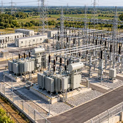
Key takeaways
- Substation design deliverables such as the single-line diagram, geotechnical report and IEEE 80 grounding study must mature before foundations and procurement can be released.
- The ground grid, foundations and duct banks are installed before steel erection so buried work is never disturbed by later heavy equipment movements.
- Oil containment for oil-immersed transformers is usually sized for the full oil volume plus margin and rainfall, following the guidance in IEEE 980.
- A 110 kV air-insulated substation typically takes one to two years from feasibility to energization, while a compact 11/0.4 kV unit can take weeks.
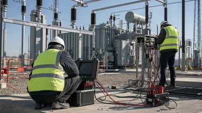
- Site commissioning covers grid resistance, transformer ratio and insulation tests, breaker timing, relay secondary injection and a written switching program for energization.
Quick answer: Substation construction is the sequence of design, permitting, civil and structural works, equipment installation, cabling, grounding, testing and energization that turns a single-line diagram into a working node of the power system. A typical project runs through feasibility, electrical and civil design, procurement of long-lead transformers and switchgear, site works, erection, commissioning tests and a controlled first energization.
Most delays in substation projects are not caused by the electrical equipment itself. They come from late geotechnical data, foundation drawings issued before vendor dimensions are frozen, grounding studies done after the site is graded, and test procedures written the week before energization. Understanding the order of work, and which decisions lock in which costs, is the most useful thing an owner or EPC engineer can bring to a project.
This guide is for utility engineers, industrial owners, EPC project managers and electrical contractors planning a new or expanded substation, from a compact 11/0.4 kV unit to an air-insulated 110 kV yard. It covers design deliverables, civil and structural engineering, installation, testing, project management and the skills and training a construction team needs.
What Does Substation Design Cover Before Construction Starts?
Substation design is the set of electrical, civil, structural and protection engineering deliverables that define what will be built, where, and how it will be tested. Construction can only move as fast as these documents mature, so it pays to know which deliverables gate which activities.
| Design deliverable | What it fixes | Construction activity it releases |
|---|---|---|
| Single-line diagram and load study | Voltage levels, transformer MVA, bus arrangement | Equipment procurement |
| General arrangement and layout | Clearances, bay spacing, roads, fence line | Site grading and survey |
| Geotechnical report | Soil bearing capacity, water table, resistivity | Foundation design |
| Grounding study (IEEE 80) | Grid conductor size, mesh spacing, rod count | Ground grid installation |
| Foundation and steel drawings | Anchor bolt patterns, pier sizes, steel loads | Concrete pours and erection |
| Protection and control schematics | Relay schemes, CT/VT ratios, interlocks | Panel wiring and cable schedules |
| Cable and conduit schedules | Routes, trench sizes, cable types | Trenching and pulling |
For high voltage substation design the layout is driven by insulation coordination and clearances, which is why air-insulated yards at 110 kV occupy far more land than gas-insulated equivalents. Our air-insulated substation design guide covers bay spacing and bus configurations, and the substation grounding grid design guide explains step and touch voltage calculations.
A substation design build contract places design and construction under one party. It shortens the schedule because foundations can be designed in parallel with procurement, but the owner must define performance requirements, standards and test acceptance criteria clearly in the employer's requirements.
Substation Civil and Structural Engineering Design
Substation civil engineering design covers grading, drainage, roads, fencing, cable trenches, oil containment and equipment foundations. Substation structural engineering design covers the steel gantries, bus supports, equipment stands and any control building. Both start from the geotechnical report and vendor-certified equipment drawings.
Key civil items
- Grading and drainage: the yard is usually graded at a shallow fall to drain away from equipment, then covered with a crushed rock surface layer that raises the surface resistivity used in the IEEE 80 touch-voltage calculation.
- Foundations: transformer slabs, drilled piers or spread footings for gantries, and plinths for switchgear and kiosks. Anchor bolt templates must match certified vendor drawings, not catalog data.
- Oil containment: pits or bunds around oil-immersed transformers, sized to hold the full oil volume plus an allowance for rainwater or fire-fighting water. IEEE 980 is the usual guide.
- Cable trenches and duct banks: separated routes for power and control cables, with pull pits at changes of direction.
Structural loads
Gantries and bus supports are designed for conductor tension, wind, ice where relevant, seismic loading and short-circuit forces. Short-circuit forces on rigid bus are calculated per IEC 60865 or IEEE 605, and they often govern insulator and support selection at high fault levels.
Worked example: oil containment volume
A transformer holds 9,500 L of mineral oil. The design adds 10% margin and a 100 mm rainfall allowance over a 6 m × 5 m pit.
V = (9,500 L × 1.10) + (6 m × 5 m × 0.10 m × 1,000 L/m³) = 10,450 + 3,000 = 13,450 L
With an effective depth of 0.6 m, the pit holds 6 × 5 × 0.6 × 1,000 = 18,000 L, which satisfies the requirement with spare capacity for fire water. Local environmental rules may require larger margins or an oil-water separator.
Electrical Substation Construction: Step-by-Step Sequence
Electrical substation construction follows a sequence that keeps buried work ahead of above-ground work, and keeps heavy equipment deliveries off finished surfaces. The order below suits most outdoor yards; compact and prefabricated substations compress several steps.
- Site survey, clearing and rough grading to the civil drawings, with temporary drainage and access.
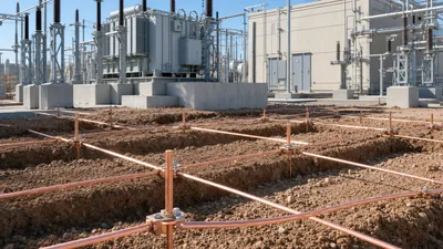
- Ground grid installation: excavate trenches, lay bare copper conductor, drive rods, make exothermic or compression joints and leave risers at every equipment location.
- Foundations and duct banks: set anchor bolt templates, pour concrete, cure, and survey bolt positions before steel arrives.
- Control building or e-house: erect the building or set a modular control house, then install battery systems, AC/DC panels and relay panels.
- Steel erection and bus work: gantries, supports, insulators, rigid or strain bus.
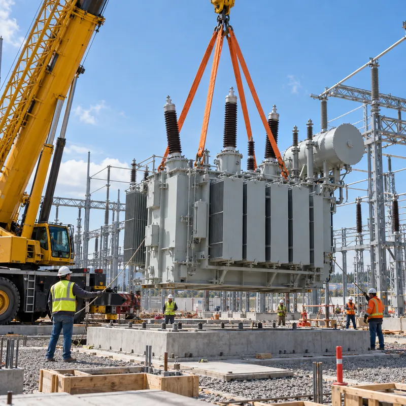
- Major equipment setting: power transformers, breakers, disconnectors, instrument transformers, surge arresters, switchgear line-ups.
- Cable pulling and termination of power and control cables, followed by point-to-point wiring checks.
- Final grading and surface rock, fence completion and fence grounding.
- Testing, commissioning and energization.
Transformers are typically the longest-lead item. A large power transformer must also be dressed on site with bushings, radiators and conservator, filled under vacuum and left to settle before testing, so its foundation and access route should be complete well before delivery. Our modular substation control house guide explains how prefabricated buildings shorten step four, and transformer pad sizing covers slab design for pad-mounted units.
Substation Building Construction and Prefabricated Options
Substation building construction refers to the enclosure that houses switchgear, protection panels, batteries and communication equipment. An electrical substation building can be cast-in-place masonry, a steel-framed building, or a factory-built modular unit delivered on a trailer.
| Approach | Typical use | Advantages | Limitations |
|---|---|---|---|
| Masonry or concrete building | Utility substations, long design life | Durable, good fire and security performance | Long site program, weather-dependent |
| Modular control house | Utility and industrial yards | Wired and tested in factory, short site time | Transport size limits |
| Compact / box-type substation | MV/LV distribution up to about 2,500 kVA | Transformer, MV and LV in one tested enclosure | Limited expansion space |
| Containerised substation | Mining, renewables, temporary supply | Relocatable, rapid installation | Thermal management must be engineered |
Building design must cover ventilation for equipment losses, battery room ventilation where vented batteries are used, cable entry, internal arc venting for switchgear tested to IEC 62271-200 internal arc classification, and fire separation. For an MV/LV distribution node, a factory-assembled unit is often the fastest route: the compact prefabricated substation buyers guide and our transformer substation range show the configurations that arrive ready for connection to a prepared plinth.
Whichever option is chosen, the civil contractor needs the certified base frame drawing, cable entry openings and lifting weights early, because plinth design and crane selection depend on them.
Testing, Commissioning and Energization
Commissioning proves that what was built matches the design and is safe to energize. It is distinct from factory routine tests, which are performed at the manufacturer before shipment. A structured approach separates individual equipment tests, functional system tests and the energization sequence.
Typical site tests
- Ground grid: fall-of-potential or similar measurement of grid resistance, and continuity checks of equipment bonds.
- Transformers: insulation resistance, turns ratio, winding resistance, oil dielectric strength and dissolved gas baseline, vector group verification.
- Circuit breakers: contact resistance, timing, insulation resistance, SF6 gas checks where applicable.
- Instrument transformers: ratio, polarity, burden, and secondary injection through to relays.
- Protection and control: relay settings verification, secondary injection, trip tests to each breaker, interlock and SCADA point-to-point checks.
- Cables: insulation resistance and, for MV cables, a withstand test such as VLF.
The substation testing engineering guide details test methods, and the site acceptance test guide explains how to structure SAT documentation so it closes out cleanly.
Energization is done under a written switching program: confirm all grounds removed, protection in service, energize the incoming line, then the transformer at no load (observing inrush and listening for abnormal noise), hold for a soak period, then pick up load in steps while checking phasing, metering and relay currents.
Substation Project Management and Construction Schedule
Substation project management is mostly interface management: between utility and owner, designer and vendors, civil and electrical contractors. The critical path almost always runs through the power transformer and the protection design.
| Phase | Indicative duration (110 kV yard) | Indicative duration (11/0.4 kV compact) |
|---|---|---|
| Feasibility, studies, utility application | 2–6 months | 2–8 weeks |
| Detailed design | 3–6 months | 2–4 weeks |
| Manufacturing of main equipment | 3–9 months depending on market | 4–7 weeks |
| Civil works and grounding | 2–4 months | 1–3 weeks |
| Erection and cabling | 2–4 months | 1–2 weeks |
| Testing and commissioning | 3–8 weeks | 2–5 days |
These durations are indicative and vary by market, utility process and equipment supply. Practical controls that keep a schedule intact:
- Freeze the single-line diagram and transformer specification before ordering, since late changes ripple through every drawing.
- Require certified vendor drawings within a contractual period after order so foundations are not designed on catalog data.
- Hold a factory acceptance test for transformers and switchgear, and agree site test sheets at that time.
- Track outage windows with the utility early; tie-in outages are often booked months ahead.
Choosing Substation Contractors and Building Skills Through Training
Substation construction companies range from full EPC firms that design, procure and build, to specialist electrical substation contractors who handle erection, wiring and testing under an owner's engineer. When comparing substation builders, check relevant voltage-class experience, a qualified testing and commissioning team, a documented safety program aligned with NFPA 70E or the local equivalent, and references for similar projects. Ask how the contractor manages interfaces with the equipment manufacturer during installation and commissioning.
Substation maintenance companies and repair specialists come in after handover. Substation repair work covers transformer oil treatment, breaker overhauls, relay replacement and damaged bus repairs, and it relies heavily on accurate as-built drawings, which is a good reason to make as-builts a contractual deliverable.
Substation training for construction and operations staff
Useful substation technician training covers switching and lockout procedures, grounding and bonding practice, equipment testing, and reading one-line and schematic drawings. Substation protection and control training adds relay principles, CT and VT circuits and functional testing. Substation maintenance training focuses on condition monitoring, oil testing and breaker maintenance. Manufacturer training during FAT and commissioning is often the most practical, because it uses the actual equipment and drawings for the site. Engineers new to the field can start with our explanation of what a substation is and does and the guide on how to read electrical drawings.
Next Steps: Specifying and Sourcing Substation Equipment
For a smooth construction phase, the equipment request for quotation should give suppliers everything they need to produce certified drawings quickly. Include:
- Single-line diagram with voltage levels, fault levels and grounding method.
- Transformer rating (kVA/MVA), vector group, impedance, cooling class, tap range, insulation and loss requirements, and governing standard (IEC 60076 or IEEE C57.12.00).
- Switchgear type and ratings: rated voltage, current, short-time withstand, internal arc classification and IEC 62271 or IEEE C37 compliance.
- Site conditions: altitude, ambient temperature range, seismic zone, pollution level and enclosure IP or NEMA rating.
- Required factory tests, FAT attendance, site supervision and spare parts.
- Delivery terms, transport limits and the site access route.
MARS supplies compact and containerised substations, power transformers to 31,500 kVA in the 110 kV class, distribution transformers and MV/LV switchgear, with routine tests on every unit and FAT welcome. Typical lead times are 25–45 days for distribution transformers and switchgear and 60–90 days for power transformers. Explore the transformer substation product range or the power transformer range, and send your single-line diagram through the quote request form for a technical and commercial offer.
Frequently asked questions
How long does substation construction take?
A compact 11/0.4 kV substation on a prepared plinth can be installed and commissioned in a few weeks once equipment arrives. A 110 kV air-insulated yard commonly takes one to two years from feasibility to energization, with the power transformer manufacturing time and utility approvals usually on the critical path. Durations vary by market and utility process.
What is the difference between substation design and substation construction?
Substation design produces the single-line diagram, layouts, grounding study, foundation drawings, protection schematics and cable schedules. Substation construction executes that design on site: grading, grounding, concrete, steel erection, equipment setting, cabling, testing and energization. In a design-build contract one company is responsible for both, which allows design and procurement to overlap.
What standards apply to substation grounding design?
IEEE 80 is the main guide for AC substation grounding and covers step and touch voltage limits, grid resistance and conductor sizing. IEC-based projects often use IEC 61936-1 and EN 50522. The grounding study needs measured soil resistivity, the maximum ground fault current and the fault clearing time to size the grid correctly.
What do electrical substation contractors do?
Electrical substation contractors install the ground grid, set equipment, erect steel and bus, pull and terminate cables, wire protection panels and run commissioning tests. Some also perform civil works and design under an EPC contract. Their scope should be defined against drawings and test sheets, with clear responsibility for interfaces with equipment suppliers.
What training does a substation technician need?
A substation technician needs training in electrical safety and switching procedures, lockout and grounding practice, reading one-line and schematic drawings, and testing of transformers, breakers, relays and instrument transformers. Protection and control training adds relay principles and secondary injection testing. Manufacturer training on the installed equipment is valuable during commissioning.
Can a prefabricated substation reduce construction time?
Yes. A compact or containerised substation arrives with transformer, MV switchgear and LV board assembled, wired and routine tested in the factory, so site work reduces to a plinth or foundation, grounding, cable connection and commissioning. This removes most building construction and much of the on-site wiring from the schedule.
Written and reviewed by the MARS application engineering team in Shanghai, who specify and test transformers, switchgear, substations and battery storage for projects in 40+ countries. Last updated .
Tags: substation construction substation design electrical substation construction substation civil engineering design substation contractors