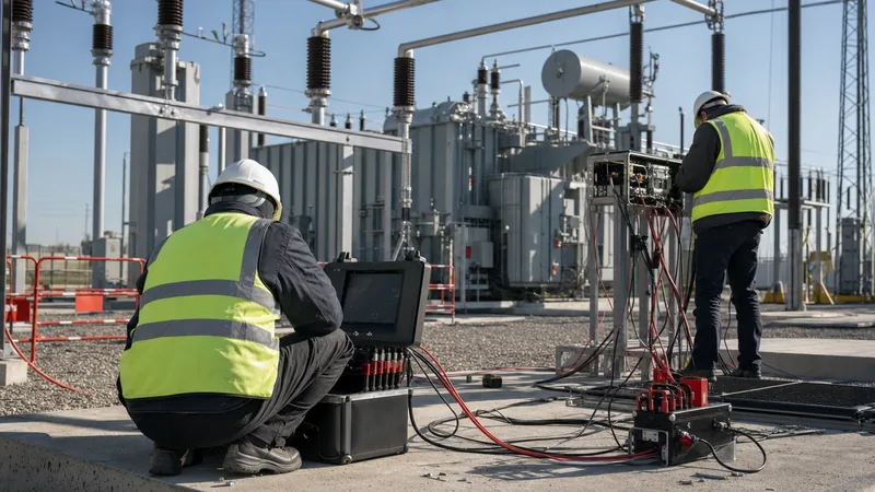
Key takeaways
- Electrical substation testing verifies insulation integrity, mechanical timing, contact resistance, and relay operating logic prior to energisation.
- Factory Acceptance Testing (FAT) validates component compliance with IEC 62271 and IEC 60076 before dispatch, whereas Site Acceptance Testing (SAT) confirms field assembly and interface integrity.
- Earth grid impedance testing using the Fall-of-Potential method per IEEE 81 ensures that actual Ground Potential Rise (GPR) remains below safe touch and step potential thresholds.
- Current transformer saturation, incorrect wiring polarity, and loose secondary neutral earthing represent the most frequent causes of protection relay failure during commissioning.
- Dielectric dissipation factor (tan delta) testing evaluates bulk insulation degradation in high-voltage transformers and bushings against a standard acceptance threshold of less than 0.5% at 20 degrees Celsius.
Quick answer: Substation testing is the systematic execution of electrical, mechanical, and diagnostic inspections designed to verify that all primary equipment, secondary protection circuits, earthing networks, and auxiliary systems operate safely within design parameters defined by standards such as IEC 62271, IEC 60076, and IEEE C37. Substation testing eliminates manufacturing defects, prevents shipping damage from causing catastrophic failures, and validates protection operation before initial energisation.
Deploying medium-voltage (MV) and high-voltage (HV) infrastructure requires rigorous quality control across every phase of installation. Whether commissioning modular plant, prefabricated substations, or conventional open-terminal switchyards, rigorous substation testing ensures that personnel remain protected and network assets deliver long-term reliability. Field failures post-energisation frequently lead to prolonged plant outages, arc flash incidents, and costly equipment replacement. A disciplined testing regime acts as the primary barrier against installation errors, thermal breakdowns, and maloperating protection systems.
This guide sets out the engineering procedures, diagnostic metrics, mathematical calculations, and acceptance criteria required for both factory and on-site testing. By adhering to internationally recognised standards, testing engineers can verify apparatus health, protect capital investments, and establish reliable baseline diagnostic data for long-term predictive maintenance.
Key stages of electrical substation testing: FAT, SAT, and commissioning
Electrical substation testing progresses across three sequential phases: Factory Acceptance Testing (FAT), Site Acceptance Testing (SAT), and final pre-energisation commissioning. Each phase targets distinct risks and isolates defects at the earliest possible stage.
Factory Acceptance Testing occurs at the manufacturer's facility under controlled laboratory and workshop conditions. During FAT, technicians carry out routine tests on major equipment—such as power transformers, disconnectors, and medium-voltage switchgear—to verify compliance with technical procurement specifications and standard manufacturing tolerances. Testing at the factory allows engineers to verify insulation levels, power loss guarantees, dielectric breakdown limits, and enclosure ingress protection before freight transport. Discovering a manufacturing fault or insulation defect on-site can delay a capital project by months; detecting it during FAT ensures immediate remediation at the point of manufacture.
Site Acceptance Testing begins once apparatus arrives on-site, has been uncrated, positioned on plinths, and mechanically coupled. Transport vibration, rough handling, humidity exposure, and site assembly variations can alter mechanical alignments or degrade dry-type and fluid insulation. SAT reproduces critical baseline diagnostic checks, such as insulation resistance and winding continuity, to identify transport damage. SAT also evaluates field-assembled items, including inter-panel busbar joints, external cable terminations, fluid refills, and site-welded earthing bonds.
Commissioning integrates the verified primary equipment with secondary systems, protection schemes, DC battery banks, SCADA networks, and civil interlocks. This phase culminates in cold commissioning (functional verification with main busbars de-energised) followed by live energisation and on-load phasing checks.
Primary equipment electrical substation testing and standard criteria
Primary equipment testing verifies the dielectric integrity, current-carrying capability, and mechanical timing of the high-voltage physical network. Failure to detect high contact resistance or degraded bulk insulation leads to thermal runaway and explosive flashovers under load.
Power transformers undergo an exhaustive series of dielectric and magnetic tests. Ratio and vector group verification per IEC 60076-1 clause 11.3 confirms correct transformation across all tap positions. Winding resistance measurements, taken with a low-resistance ohmmeter injecting direct current, detect loose internal connections, broken strands, or poor tap changer contact surfaces. For detailed diagnostic procedures on large coils and fluid metrics, consult our technical guide on power transformer testing.
Circuit breakers require mechanical motion analysis and static contact resistance measurement. Operating timing tests, conducted in accordance with IEC 62271-100, record contact opening, closing, and open-close-open (OCO) cycle times down to the millisecond. Deviations greater than 2 ms between poles (pole pole spread) induce severe transient recovery voltages and phase imbalance. Static contact resistance is assessed using a calibrated micro-ohmmeter delivering a regulated direct current of at least 100 A DC to eliminate oxide skin effects, per IEC 62271-1 clause 6.4.4.
Instrument transformers (CTs and VTs) dictate protection relay performance. Current transformers undergo saturation (excitation curve) testing, winding resistance measurement, ratio error checks, and polarity verification using the flicker method or variable AC injection. Voltage transformers are evaluated for winding ratio, phase angle error, and secondary winding burden tolerance according to IEC 61869-2 and IEC 61869-3.
| Primary Equipment | Diagnostic Test Parameter | Reference Standard | Acceptance Criteria |
|---|---|---|---|
| Power Transformer | Winding Resistance | IEC 60076-1 clause 11.2 | Within 2% deviation between phases; <1% from FAT values |
| Power Transformer | Voltage Ratio & Vector Group | IEC 60076-1 clause 11.3 | Ratio error < 0.5% of nameplate on all tap positions |
| HV/MV Circuit Breaker | Static Contact Resistance | IEC 62271-100 / IEEE C37.09 | Values within 20% of factory baseline; typically < 50 micro-ohms |
| HV/MV Circuit Breaker | Simultaneous Pole Timing | IEC 62271-100 clause 6.101 | Pole-to-pole discrepancy < 3.3 ms (opening), < 5 ms (closing) |
| Current Transformer (CT) | Excitation (Knee-Point) | IEC 61869-2 clause 7.2 | Knee-point voltage matches design; 10% voltage increase gives <50% current increase |
| Voltage Transformer (VT) | Ratio and Polarity | IEC 61869-3 clause 7.2 | Ratio error < 0.5% (protection class 3P); subtractive polarity confirmed |
| Disconnectors & Earth Switches | Contact Resistance & Interlocking | IEC 62271-102 clause 6.4 | Resistance within manufacturer limits; mechanical interlocks 100% fail-safe |
Secondary injection and substation protection relay testing
Secondary injection testing isolates and validates the protection relays, trip circuits, auxiliary logic, and current/voltage secondary wiring without applying high voltage to the primary plant. Modern numerical relays require precise automated test sets capable of multi-phase current and voltage output to verify complex algorithm settings.
Testing begins with visual inspections of wiring diagrams and terminal block crimping, followed by DC burden checks. Engineers apply secondary injection directly to relay terminal blocks using a computerised three-phase test set. Configured protective elements—such as overcurrent (50/51), earth fault (50N/51N), directional overcurrent (67), distance (21), and differential (87)—are challenged across their programmed trip characteristics. Current pick-up thresholds and time-delay curves must operate within +/- 3% of the protection coordination study parameters.
For complex network architectures and parallel incoming feeders, protection schemes rely on fast communication between substations. Line differential and permissive overreach transfer trip (POTT) schemes require end-to-end testing synchronised via GPS time clocks. GPS-synchronised test sets inject simulated dynamic fault conditions at both line terminations simultaneously. This verifies that current vectors, propagation delays, and digital communications channels operate coherently under out-of-zone and in-zone fault scenarios. For a deeper analysis of relay selection and trip curves, refer to our substation protection engineering guide.
Finally, trip testing must never terminate at the relay output contact. Every protection test must trip the designated circuit breaker, initiate auto-reclose cycles where applicable, flag the alarm annunciation panel, drive breaker-fail schemes (50BF), and transmit the digital sequence-of-events log over IEC 61850 or Modbus protocols to the local human-machine interface (HMI).
Substation earth grid and soil resistivity testing
Substation earth grid testing measures the physical capability of the buried grounding network to dissipate high fault currents safely into the mass of the earth without generating lethal surface potentials. Inadequate grounding networks cause hazardous step and touch potentials during phase-to-ground faults, exposing maintenance crew and passers-by to fatal electric shocks.
Soil resistivity surveys, performed during the civil design stage using the Wenner four-pin method (IEEE 81), provide the soil structure profile used to model grid geometry. Following construction and civil backfilling, the completed earth grid must be physically tested. The recognised industry standard is the Fall-of-Potential method. An auxiliary current probe is driven into the earth at a significant distance from the grid—typically five to ten times the maximum diagonal dimension of the substation grounding field—to ensure that the resistance areas of the grid and the probe do not overlap.
A potential probe is then driven at intermediate points along the straight-line path between the substation grid and the current probe. By plotting measured resistance against distance, engineers identify the characteristic flat plateau of the true earth resistance. The true ground resistance of a major substation should ideally remain below 1.0 ohm; for large industrial and transmission plants, values below 0.5 ohms are standard practice.
Bonding continuity tests must also be performed on every steel column, equipment tank, switchgear enclosure, surge arrester base, and metallic boundary fence. Injecting 10 A to 20 A DC between individual apparatus frames and the main ground grid ring confirms that bonding paths maintain low impedance, typically exhibiting values under 0.1 ohm.
Insulation resistance, power factor, and dielectric testing
Dielectric diagnostic testing validates the integrity of bulk insulation systems across high-voltage cables, switchgear busbars, transformers, and instrument bushings. Environmental humidity, ionic contamination, mechanical micro-cracking, and void formations all degrade dielectric withstand capability.
Insulation Resistance (IR) testing represents the baseline screening check. Performed with a calibrated megohmmeter applying 1,000 V to 10,000 V DC depending on the nominal system voltage, IR testing measures the total leakage current through and across the insulation surface. The Polarization Index (PI) is calculated by dividing the 10-minute resistance reading by the 1-minute reading:
PI = R10min / R1min
In standard oil-immersed or resin-cast equipment, a PI value greater than 2.0 indicates dry, uncontaminated insulation, whereas values below 1.5 signify absorbed moisture or surface tracking paths. The Dielectric Absorption Ratio (DAR), calculated as R60s / R30s, provides an accelerated assessment for compact assets.
Power Factor (tan delta) testing uses alternating current to evaluate bulk dielectric losses within transformers, bushings, and MV cables. By applying an AC voltage (typically 10 kV) at power frequency, the test set resolves total current into resistive (loss) and capacitive components. The ratio of resistive loss current to capacitive current defines the dissipation factor:
tan δ = IR / IC
New oil-immersed transformers and modern resin-impregnated paper (RIP) bushings typically exhibit tan delta values well below 0.5% at 20 degrees Celsius. Bushings exhibiting dissipation factors above 1.0% indicate critical moisture ingress or carbon tracking and warrant immediate replacement.
High-potential (Hi-Pot) withstand testing provides final confirmation of dielectric clearance. For extruded dielectric medium-voltage cables (such as XLPE), Very Low Frequency (VLF) AC testing at 0.1 Hz per IEEE 400.2 has replaced destructive DC testing. VLF testing subjects the cable insulation to peak operational electric stresses without injecting harmful space-charge packets that trigger premature cable breakdown.
Step-by-step site acceptance testing (SAT) checklist
A structured site acceptance testing checklist ensures that no safety interlock, mechanical assembly, or electrical parameter is overlooked during field commissioning. The following sequential workflow must be executed by certified commissioning personnel prior to system energisation:
- Civil and environmental verification: Inspect cable trench drainage, plinth curing certificates, equipment anchorage bolting torque, and switchroom HVAC pressurisation before uncrating sensitive secondary equipment.
- Earth grid connection inspection: Verify that all equipment tanks, cable sheaths, metal framing, and surge arresters are bonded to the subterranean earth grid with double-bolted or exothermic connections, recording bonding resistance < 0.1 ohm.
- Visual and mechanical checks: Inspect primary porcelain and composite bushings for micro-fissures, check transformer fluid levels, inspect conservator desiccant breather colour, verify SF6 gas pressure gauges against temperature compensation curves, and confirm panel paint finish integrity.
- Primary insulation and dielectric screening: Execute 5 kV / 10 kV DC insulation resistance and polarisation index measurements on all phases, recording baseline temperature and relative humidity. Perform VLF withstand tests on MV cables and power factor tests on power transformer windings and high-voltage bushings.
- Primary contact and winding resistance: Measure static contact resistance on circuit breaker poles and busbar splice joints using a 100 A DC micro-ohmmeter. Measure transformer DC winding resistance across all tap changer positions, recording oil and ambient temperatures for resistance temperature correction to 75 degrees Celsius.
- Instrument transformer performance verification: Perform excitation knee-point plotting, winding resistance, secondary burden, voltage ratio, and polarity checks on all current and potential transformers. Confirm that all unused current transformer secondary cores are securely shorted and bonded to earth at a single point.
- Protection relay secondary injection: Inject calibrated currents and voltages across all relay modules, verifying pick-up settings, time-current trip curves, directional logic, and differential restraint characteristics. Validate digital GOOSE messaging and interlocking via IEC 61850 communications channels.
- Trip circuit and breaker operational timing: Electrically trip every breaker via its associated protection relay, verifying breaker auxiliary contacts, anti-pumping circuits, trip-circuit supervision (TCS) relays, SCADA alarm flags, and mechanical open/close time parameters.
- Auxiliary DC supply and interlock verification: Conduct discharge load testing on the substation 110 V or 220 V DC station battery bank, test the automatic battery float charger, and rigorously verify all electrical, mechanical, and Castell key interlock sequences.
- Final pre-energisation walk-down: Remove all temporary portable safety earthing leads, remove injection test jumpers, ensure panel tools and test gear are accounted for, inspect busbar clearances, check enclosure sealing, and issue the formal handover permit to energise.
Worked calculation: earth grid touch and step potential verification
Evaluating the safety of a substation earthing grid requires calculating the allowable touch and step voltage limits and comparing them against the calculated mesh and step potentials generated during a maximum line-to-ground fault, according to IEEE 80. The following worked calculation illustrates this design verification process for an MV/HV substation.
Consider an electrical substation testing project with the following site parameters:
- System fault current (single line-to-ground), IF = 12,000 A (12 kA)
- Fault duration, ts = 0.5 s
- Substation surface layer material: 100 mm (0.10 m) of crushed rock with resistivity ρs = 2,500 Ω·m
- Native soil resistivity, ρ = 120 Ω·m
- Surface layer derating factor, Cs = 0.78
- Assumed human body mass = 70 kg
- Measured substation grid resistance, Rg = 0.42 Ω
- Grid current division factor (current escaping directly to grid), Sf = 0.60
First, calculate the allowable touch voltage (Etouch70) for a 70 kg person according to IEEE 80 clause 8.4:
Etouch70 = (1000 + 1.5 × Cs × ρs) × 0.157 / √ts
Substitute the project values into the equation:
Etouch70 = [1000 + 1.5 × (0.78 × 2,500)] × (0.157 / √0.5)
Etouch70 = [1000 + 2,925] × (0.157 / 0.7071) = 3,925 × 0.2220 = 871.4 V
Next, determine the maximum allowable step voltage (Estep70) across a 1.0 m pace length:
Estep70 = (1000 + 6.0 × Cs × ρs) × 0.157 / √ts
Estep70 = [1000 + 6.0 × (0.78 × 2,500)] × 0.2220
Estep70 = [1000 + 11,700] × 0.2220 = 12,700 × 0.2220 = 2,819.4 V
Now determine the total grid current (Ig) flowing directly into the earth via the grounding grid:
Ig = IF × Sf = 12,000 A × 0.60 = 7,200 A
Calculate the Ground Potential Rise (GPR):
GPR = Ig × Rg = 7,200 A × 0.42 Ω = 3,024.0 V
Because the GPR (3,024.0 V) exceeds the allowable touch voltage limit (871.4 V), detailed mesh voltage (Em) field calculations must be conducted. During testing, field measurements using simulated low-current injection show a maximum mesh voltage percentage of 24% of the GPR:
Em = GPR × 0.24 = 3,024.0 V × 0.24 = 725.8 V
Comparing the calculated actual mesh voltage against the allowable touch limit:
Em (725.8 V) < Etouch70 (871.4 V) → COMPLIANT (PASS)
The earthing grid design and site installation are confirmed safe for operating personnel under maximum phase-to-ground fault conditions.
Common field testing pitfalls and diagnostic troubleshooting
Field testing frequently exposes subtle defects that, if left unaddressed, lead to spurious trips or catastrophic failure upon initial energisation. Commissioning teams must recognise and resolve these conditions systematically.
A widespread defect during secondary scheme commissioning is multiple earthing points on current transformer circuits. According to IEC 61869-2, a CT secondary circuit must be earthed at exactly one physical location—typically at the first protection relay marshalling cabinet. If secondary wiring is earthed at both the outdoor junction box and the indoor protection cubicle, circulating stray ground currents induce false differential currents. This phenomenon causes high-speed differential relays (87) to maloperate during external through-faults or upon system energisation.
Another common issue is elevated contact resistance across medium-voltage switchgear busbar joints. Field installation teams often rely on uncalibrated mechanical torque wrenches or fail to properly clean silver-plated copper contact surfaces before bolting. A micro-ohm reading that deviates by more than 20% from adjacent bus joints indicates inadequate bolt tension or surface oxidation. Under continuous operating currents of 1,250 A or 2,500 A, this marginal resistance causes localised thermal runaway, melting insulation barriers and culminating in severe internal arc incidents. Regular reference to standard transformer maintenance and testing procedures helps teams identify these contact resistance degradation profiles.
Current transformer saturation curve testing also reveals mislabelled or swapped cores. In multi-core CTs featuring both measurement and protection cores, connecting a differential relay to a measurement core (which saturates early to protect sensitive instruments) causes complete relay blindness during severe high-magnitude fault currents. Ensuring that knee-point voltage curves match the protection coordination specification guarantees relay stability under fault conditions.
Next steps: specifying and sourcing
Precise electrical substation testing specifications eliminate ambiguity, prevent costly on-site disputes, and ensure delivered equipment complies strictly with your network fault ratings. When preparing requests for quotation (RFQs) for turnkey substations or modular power distribution packages, always specify required FAT and SAT protocols explicitly, citing relevant IEC 62271, IEC 60076, and IEEE C37 standards.
To accelerate your project timelines, review our engineered range of prefabricated transformer substations and high-reliability HV and LV switchgear assemblies, all supplied with fully certified factory routine test dossiers. For bespoke engineering reviews or to obtain formal equipment quotes accompanied by tailored inspection and testing plans (ITP), submit your single-line diagrams directly via our online quotation request page.
Frequently asked questions
What is the difference between FAT and SAT in substation testing?
Factory Acceptance Testing (FAT) evaluates individual equipment compliance against technical standards at the manufacturer facility prior to delivery. Site Acceptance Testing (SAT) verifies that apparatus has suffered no shipping damage, has been correctly installed, and interfaces reliably with surrounding on-site systems prior to energisation.
Why is current transformer polarity testing critical during substation commissioning?
Current transformer polarity testing verifies the correct orientation of secondary currents relative to primary flow. Reversed polarity causes directional and differential relays to interpret normal load or external faults as internal in-zone faults, causing immediate false trips upon energisation.
What is an acceptable earth grid resistance value for an electrical substation?
An acceptable earth grid resistance for major distribution and transmission substations is generally less than 1.0 ohm, with large facilities targeting less than 0.5 ohms. However, compliance ultimately depends on verified touch and step potential limits calculated under IEEE 80.
How does tan delta testing detect insulation degradation?
Tan delta testing measures the ratio of resistive leakage current to capacitive charging current when an AC voltage is applied. As bulk insulation degrades due to moisture ingress, thermal aging, or chemical breakdown, resistive leakage increases, raising the dissipation factor above standard threshold limits.
What standards govern electrical substation testing procedures?
Primary equipment and substation testing procedures are governed by IEC 62271 for switchgear, IEC 60076 for power transformers, IEC 61869 for instrument transformers, IEEE 81 and IEEE 80 for grounding networks, and IEEE C37 series for switchgear and protection coordination.
Tags: substation testing electrical substation testing switchgear commissioning protection relay testing site acceptance testing


