Key takeaways
- An air insulated substation uses atmospheric ambient air as its primary phase-to-phase and phase-to-earth dielectric medium.
- Electrical clearances in an AIS switchyard are governed by IEC 61936-1 and IEC 60071-1, dictated directly by rated lightning impulse withstand voltage (BIL).
- For a 145 kV system with a 650 kV BIL, minimum phase-to-earth clearance is 1,100 mm and minimum phase-to-phase clearance is 1,300 mm.
- While AIS facilities require up to 85% more land footprint than gas-insulated alternatives, initial equipment CAPEX is substantially lower.
- Busbar topologies such as breaker-and-a-half provide superior operational reliability and maintenance isolation over single-bus configurations.
Quick answer: An air insulated substation is an electrical installation where ambient atmospheric air serves as the external dielectric insulation medium between high-voltage conductors, ground structures, and adjacent electrical phases. Typically deployed outdoors across distribution and transmission voltages from 11 kV to 765 kV, an air insulated substation provides low capital expenditure and direct visual component access, though it demands substantial physical ground area.
High-voltage transmission and distribution systems rely on substations to route power, sectionalise faults, and step voltages down for industrial and municipal distribution. Inside an air insulated substation (AIS), all active exposed live parts—including rigid or flexible busbars, disconnectors, and instrument transformers—rely on spatial separation to prevent dielectric breakdown. Understanding the governing standards, layout topologies, minimum electrical clearances, and operational maintenance schedules is essential for consulting engineers, utility planners, and EPC contractors developing utility-scale electrical networks.
What Is an Air Insulated Substation and How Does It Operate?
An air insulated substation is an electrical facility where atmospheric air at ambient pressure provides the primary electrical insulation between bare conductors and earthed structural steelwork. Unlike sealed installations that enclose live parts within pressurised dielectric gases or solid insulation, an AIS isolates potential differences through physical air gaps that exceed the electrical breakdown strength of atmospheric air under standard environmental conditions.
Atmospheric air exhibits a dielectric breakdown strength of approximately 3 kV per millimetre under uniform field conditions at standard temperature and pressure. In practice, conductor geometry, atmospheric pollution, humidity, and barometric elevation lower this threshold considerably. As a result, engineering an AIS requires strictly calculated phase-to-earth and phase-to-phase clearances established under IEC 60071-1 (Insulation co-ordination) and IEC 61936-1 (Power installations exceeding 1 kV AC). While medium-voltage installations frequently incorporate indoor air insulated switchgear within prefabricated shelters or buildings, high-voltage installations operate primarily as outdoor switchyards where structural steel gantries support bare tubular aluminium or flexible stranded conductors.
Key Components of an AIS Switchyard
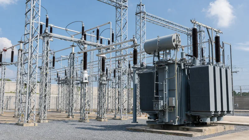
An outdoor ais switchyard integrates distinct primary switching, measurement, protection, and transformation apparatus arranged across dedicated bays. Each bay serves a distinct transmission line, power transformer, capacitor bank, or bus-tie circuit.
The primary high-voltage equipment deployed within an AIS switchyard includes:
- Power Transformers: Step-up or step-down units that convert transmission-level voltages to medium distribution voltages, often paired with neutral earthing reactors.
- High-Voltage Circuit Breakers: Interruption equipment utilising vacuum or sulphur hexafluoride (SF6) arc-quenching chambers to break load and short-circuit fault currents up to 63 kA.
- Disconnectors and Earthing Switches: Motor-operated or manual isolators providing an open, visible isolation gap compliant with IEC 62271-102 to ensure personnel safety during maintenance.
- Instrument Transformers: Inductive or capacitive voltage transformers (VTs) and wound-type current transformers (CTs) stepping down primary system parameters to 110 V and 1 A or 5 A secondary signals for protection relays.
- Surge Arresters: Metal-oxide varistor (MOV) arresters positioned close to transformer bushings and line entries to suppress transient lightning and switching overvoltages.
- Busbar Systems: Solid aluminium tubes (such as 6063-T6 alloy) supported by post insulators, or flexible stranded aluminium conductors (ACSR/AAAC) tensioned between structural steel lattice or tubular gantries.
Clearance and Sizing Calculations for AIS Substations
Electrical clearances dictate the footprint and physical geometry of ais substations. If clearances fail to meet statutory electrical safety margins, transient switching impulses or atmospheric lightning will cause flashovers across phases or to earth structures.
According to IEC 61936-1 clause 5.1, clearances depend directly on the rated lightning impulse withstand voltage (BIL) and the rated switching impulse withstand voltage. The two fundamental dimensions are the minimum phase-to-earth clearance ($N$) and the minimum phase-to-phase clearance ($P$). Working safety clearance ($B$) defines the boundary required to allow maintenance personnel to safely approach live apparatus without flashover risks, calculated as: $B = N + 2250\text{ mm}$, where 2250 mm represents the reach of a worker plus an ergonomic safety envelope.
Consider a 132 kV transmission AIS switchyard design:
- Nominal system voltage ($U_n$): 132 kV
- Highest voltage for equipment ($U_m$): 145 kV
- Rated Lightning Impulse Withstand Voltage (BIL, 1.2/50 μs): 650 kV peak
- Power-frequency short-duration withstand (50 Hz, 1 min): 275 kV RMS
From IEC 61936-1 Table 1, the design parameters must satisfy:
- Minimum phase-to-earth clearance ($N$): 1,100 mm
- Minimum phase-to-phase clearance ($P$): 1,300 mm
- Minimum safety working clearance to vehicle/pedestrian ground ($B$): $1,100\text{ mm} + 2,250\text{ mm} = 3,350\text{ mm}$
- Minimum height of live conductor above access roads: $B + 750\text{ mm} = 4,100\text{ mm}$ (typically specified at 6,000 mm minimum to accommodate mobile access cranes)
For installations situated above 1,000 metres elevation, IEC 60071-1 clause 4.2 requires multiplying these clearance distances by an altitude correction factor ($k_a = e^{m(H-1000)/8150}$, where $H$ is altitude in metres and $m$ is a factor depending on impulse characteristics) to compensate for reduced air density.
Standard Electrical Clearances Table for AIS Switchyards
The table below provides minimum phase-to-earth, phase-to-phase, and ground safety clearances across standard AC voltage ratings in accordance with IEC 61936-1 and common utility engineering practices.
| Nominal Voltage ($U_n$) [kV] | Highest System Voltage ($U_m$) [kV] | Rated BIL (Peak) [kV] | Min Phase-to-Earth Clearance ($N$) [mm] | Min Phase-to-Phase Clearance ($P$) [mm] | Min Personnel Safety Height ($B$) [mm] |
|---|---|---|---|---|---|
| 11 / 22 | 24 | 125 | 220 | 250 | 2,470 |
| 33 | 36 | 170 | 320 | 370 | 2,570 |
| 66 | 72.5 | 325 | 630 | 720 | 2,880 |
| 110 / 132 | 145 | 650 | 1,100 | 1,300 | 3,350 |
| 220 | 245 | 1,050 | 1,900 | 2,400 | 4,150 |
| 400 | 420 | 1,425 | 3,400 | 4,200 | 5,650 |
Air Insulated Substation vs Gas Insulated Substation (GIS)
Deciding between an air insulated substation and a gas insulated substation involves trade-offs between initial capital outlay, site land availability, environmental conditions, and maintenance costs. While an AIS relies on ambient air, a GIS seals conductors within aluminium enclosures pressurised with sulphur hexafluoride (SF6) or alternative fluoronitrile gas mixtures, as detailed in our guide to gas insulated switchgear engineering.
| Design Parameter | Air Insulated Substation (AIS) | Gas Insulated Substation (GIS) |
|---|---|---|
| Footprint Requirement | Baseline (100% area); requires wide inter-phase spacing | 10% to 15% of equivalent AIS land area |
| Initial Equipment CAPEX | Lowest capital cost for primary high-voltage equipment | 1.5x to 2.5x higher equipment procurement expenditure |
| Civil Works & Site Prep | Extensive grading, earthworks, and multiple concrete equipment pads | Single compact building foundation or indoor slab |
| Environmental Exposure | Vulnerable to salt fog, industrial pollution, dust, and icing | Hermetically sealed; immune to outdoor atmospheric pollution |
| Maintenance & Accessibility | Direct visual inspection; straightforward mechanical repairs | Requires specialized gas handling equipment and sectional gas cart evacuations |
| Expansion Flexibility | Simple to extend bays if perimeter land is available | Challenging; requires matching existing manufacturer bus enclosures |
For rural installations, mining networks, and industrial developments where land costs remain moderate, an air insulated substation provides the most cost-effective lifecycle economics. Conversely, inner-city hubs, offshore wind substations, and severe coastal environments often justify the higher CAPEX of GIS or indoor metal clad switchgear architectures.
Busbar Configurations for AIS Substations
Busbar architecture determines the operational operational security, maintenance flexibility, and cost of ais substations. Engineers select configurations based on system critical rating and fault level criteria.
- Single Busbar Scheme: The simplest arrangement with all outgoing and incoming bays connected to a solitary common bus. While capital cost is minimal, maintaining the busbar requires a total station outage.
- Double Busbar Scheme: Features two independent main busbars with bus-coupler circuit breakers. Feeders can be transferred between busbars without interrupting power using disconnectors, providing operational security during maintenance.
- Breaker-and-a-Half Scheme: Consists of three circuit breakers feeding two separate circuits between two main busbars (an average of 1.5 breakers per circuit). Heavily utilised in 220 kV to 765 kV transmission switchyards, this scheme enables breaker maintenance without taking any line or busbar out of service.
- Ring Busbar Scheme: Breakers form a closed loop with circuits tapped between adjacent breakers. If a circuit breaker fails, selective tripping isolates only that breaker while maintaining supply to all feeders, making it suitable for critical generation switchyards.
To safeguard these topologies against fault conditions, designers implement dedicated differential busbar and feeder schemes, which are detailed in our guide to substation protection engineering.
Inspection, Testing, and Commissioning Procedures
Pre-commissioning and site acceptance testing (SAT) confirm that all primary equipment, structural mountings, and grounding grids within an AIS switchyard meet design specifications and regulatory limits before energisation.
Field commissioning teams follow systematic site testing sequences, as covered in our substation testing guide:
- Earth Grid Integrity Testing: Measure touch and step voltages and verify grounding grid continuity using a high-current injection test set in compliance with IEEE Std 80.
- Insulation Resistance and Dielectric Withstand: Perform 5 kV DC insulation resistance tests across post insulators, busbars, and instrument transformers, followed by high-voltage AC withstand testing per IEC 60060-1.
- Contact Resistance Testing (Micro-Ohm Measurement): Measure the dynamic and static contact resistance across circuit breaker interrupters and disconnector blades using a 100 A DC micro-ohmmeter; contact resistance should typically not exceed 40 to 60 micro-ohms.
- Instrument Transformer Calibration: Execute excitation, ratio, polarity, and secondary winding resistance tests on CTs and VTs per IEC 61869-2 to ensure accuracy classes match protection relay settings.
- Breaker Timing and Motion Analysis: Measure opening, closing, and trip-free operational times to verify synchronism across all three poles within ±2 milliseconds.
Next steps: specifying and sourcing
When preparing technical tender documentation or an RFQ for an air insulated substation, provide comprehensive site ambient parameters including minimum and maximum design temperatures, seismic peak ground acceleration, maximum wind speed, altitude, and site pollution severity (SPS) according to IEC 60815. Detail your system single-line diagram (SLD), short-circuit withstand rating (kA for 1s or 3s), rated continuous busbar current, and BIL requirements.
To support your substation deployment, explore our factory-tested power transformers, outdoor prefabricated transformer substations, and complementary HV and LV switchgear assemblies. Contact our technical engineering team at [email protected] or request a dedicated proposal through our substation quote portal.
Frequently asked questions
What is the difference between AIS and GIS substations?
An air insulated substation uses atmospheric air as its primary insulating medium between uninsulated phase conductors and earthed structures, requiring wide safety clearances and large land plots. A gas insulated substation encloses all conductors within sealed aluminium compartments pressurised with dielectric gas (such as SF6), reducing the station footprint by up to 85%.
What are the standard clearances for a 132 kV air insulated substation?
Under IEC 61936-1 for a 132 kV system with a rated lightning impulse withstand voltage (BIL) of 650 kV, the minimum phase-to-earth clearance is 1,100 mm, and the minimum phase-to-phase clearance is 1,300 mm. The safety working boundary for ground personnel is 3,350 mm.
What causes dielectric breakdown in an air insulated substation?
Dielectric breakdown occurs when the electric field strength between energized conductors and earth exceeds the breakdown strength of atmospheric air (nominally 3 kV/mm under uniform conditions). Breakdown is accelerated by transient lightning or switching overvoltages, reduced air density at high elevations, humidity, and atmospheric pollution deposits on insulator surfaces.
Which busbar scheme is best for high-voltage AIS switchyards?
The breaker-and-a-half scheme is widely considered the best architecture for critical high-voltage transmission switchyards operating above 132 kV. It utilizes three circuit breakers for every two circuits, allowing any circuit breaker or busbar to be taken offline for maintenance without disrupting feeder power delivery.
How does elevation affect air insulated substation clearances?
Higher elevations experience lower atmospheric pressure and decreased air density, which reduces the dielectric withstand strength of air gaps. For substations located higher than 1,000 metres above sea level, IEC 60071-1 requires applying an altitude correction factor to increase physical phase-to-earth and phase-to-phase clearances.
Tags: air insulated substation ais substations ais switchyard substation engineering switchgear


