Key takeaways
- A gas insulated switchgear reduces substation footprint by 85% to 90% compared to equivalent air-insulated switchgear installations.
- IEC 62271-203 mandates factory gas leakage rates below 0.5% per year over the operational lifetime of the equipment.
- Sulphur hexafluoride (SF6) operates at typical absolute pressures between 0.35 MPa and 0.70 MPa, providing roughly three times the dielectric strength of atmospheric air.
- Routine dielectric acceptance testing requires high-voltage power-frequency withstand alongside partial discharge measurements kept strictly below 5 pC per compartment.
- Integrated earth switches with high-speed making capability (Class E1 or E2) are mandatory for busbar and line-feeder safety during maintenance.
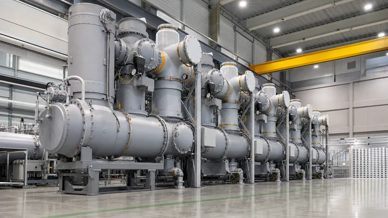
Quick answer: A gas insulated switchgear (GIS) is a compact, metal-encapsulated high-voltage switchgear assembly that uses sulphur hexafluoride (SF6) or alternative fluoronitrile gas mixtures under pressure as the primary dielectric and arc-quenching medium. It consolidates circuit breakers, disconnectors, earth switches, and instrument transformers into grounded aluminium or steel enclosures, cutting physical land requirements by up to 90% compared to conventional air-insulated installations.
High-voltage transmission grids, offshore wind platforms, and constrained urban substations face severe spatial and environmental constraints. Conventional air clearance rules dictate wide phase-to-phase and phase-to-earth separations. Where space is at a premium or atmospheric pollution poses flashover hazards, engineers specify an SF6 gas switchgear arrangement. Understanding the mechanical architecture, gas management standards, and routine commissioning protocols ensures reliable lifecycle operation without unplanned outages.
How a Gas Insulated System Works: Architecture and Components
A gas insulated system operates by enclosing all active high-voltage conductors inside grounded, sealed metal chambers pressurised with dielectric gas. The high dielectric strength of the gas permits phase-to-ground clearances of mere centimetres rather than the multiple metres required in atmospheric air, governed by IEC 62271-203 (covering gas-insulated metal-enclosed switchgear for rated voltages above 52 kV).
The assembly integrates primary electrical apparatus within compartmentalised modules isolated by gastight epoxy resin barrier insulators:
- Circuit Breakers: Utilize self-blast or puffer interrupter chambers to extinguish switching arcs within milliseconds under SF6 pressure between 0.50 MPa and 0.70 MPa absolute.
- Disconnectors and Earthing Switches: Motor-driven mechanisms providing visible isolation indicators and high-speed earthing capability capable of closing against full prospective short-circuit currents.
- Instrument Transformers: Inductive or optical current transformers (CTs) mounted externally around non-magnetic casing sections, alongside gastight inductive voltage transformers (VTs).
- Cable Terminations and Bushings: Fluid-free or dry-type plug-in terminations connecting the gis electrical system directly to cross-linked polyethylene (XLPE) underground cables or gas-to-air outdoor bushings.
- Rupture Discs: Calibrated non-fragmenting bursting discs directed away from operating aisles to prevent catastrophic casing overpressure during internal arcing events, compliant with IEC 62271-203 clause 6.104.
Gas Insulated Switchgear vs Air Insulated Switchgear
Choosing between gis switchgear and traditional switchgear depends on available ground area, site contamination levels, and total project lifecycle cost. While an open-terminal substation requires substantial civil clearance zones, a gas insulated substation houses high-voltage bays within standard industrial buildings or underground vaults.
The engineering trade-offs between air-insulated technology and encapsulated gas solutions are detailed below:
| Engineering Parameter | Air Insulated Switchgear (AIS) | Gas Insulated Switchgear (GIS) |
|---|---|---|
| Footprint Requirement (145 kV Bay) | 100% (approx. 120–150 m²) | 10% to 15% (approx. 12–18 m²) |
| Dielectric Medium | Atmospheric air at ambient pressure | Pressurised SF6 or eco-gas (0.4–0.6 MPa) |
| Environmental Sensitivity | High (salt spray, dust, humidity, bird strikes) | Negligible (hermetically sealed compartments) |
| Rated Busbar Current | Up to 4,000 A | Up to 6,300 A (forced or natural convection) |
| Short-Time Withstand (1 s / 3 s) | 31.5 kA to 50 kA | 40 kA to 63 kA (custom to 80 kA) |
| Major Overhaul Frequency | 5 to 10 years | 25 to 30 years (visual & gas checks only) |
| Initial Capital Expenditure (CAPEX) | Lower baseline equipment cost | 40% to 80% higher equipment cost |
| Site Civil Works Cost | High (large earthworks, fencing, civil foundations) | Low (compact indoor foundation slab) |
For a detailed breakdown of atmospheric air clearance calculations and structural configurations, consult our guide to air insulated switchgear engineering.
Dielectric Design and Gas Monitoring in GIS Power System Installations
Gas pressure and density determine the dielectric integrity of any gis power system. Because dielectric breakdown voltage depends on molar gas density rather than simple gauge pressure, monitoring systems must track temperature-compensated density rather than raw pressure to prevent false low-gas alarms during winter temperature drops.
Dielectric strength in SF6 follows Paschen's Law adjusted for electronegative gases. At 0.45 MPa absolute pressure ($p$), the breakdown field strength ($E_{cr}$) of SF6 is approximately:
$$\frac{E_{cr}}{p} \approx 89 \text{ kV}/(\text{mm}\cdot\text{MPa})$$
For a 145 kV system with a rated lightning impulse withstand voltage (BIL) of 650 kV crest per IEC 60071-1, an operating gas pressure of 0.45 MPa yields an intrinsic dielectric strength exceeding 40 kV/mm. This enables coaxial conductor-to-enclosure clearances below 90 mm.
Engineering monitoring practices mandate temperature-compensated gas density monitors with two-stage electromechanical contacts:
- Stage 1 (Warning): Set at 95% of nominal density (typically 0.42 MPa abs). Triggers an automated alarm on the central SCADA system while maintaining rated insulation and full interruption capability.
- Stage 2 (Trip / Lockout): Set at 90% of nominal density (typically 0.38 MPa abs). Locks the circuit breaker trip-and-close coils to avoid interrupting faults under inadequate dielectric quenching capacity.
Engineering a Gas Insulated Substation for GIS Power Plant Applications
Integrating switchgear within a gis power plant or heavy manufacturing facility demands strict coordination between civil structural loading, cable raceways, and thermal dissipation. Compact gas insulated switchgear high voltage products allow co-locating the main substation immediately adjacent to generation turbines or industrial loads, reducing expensive medium-voltage and high-voltage bus duct runs.
Key structural and installation criteria for a reliable gis ss include:
- Floor Slab Deflection: Concrete floors supporting GIS bays must maintain a strict flatness tolerance within 2 mm over a 2-metre span, with structural deflection limited to under 1/1000 of the bay span to prevent shearing stresses on internal gas seals.
- Earthing Grids: High-frequency transient overvoltages (VFTs) generated during disconnect operations induce transient enclosure voltages. Solid multi-point grounding must connect switchgear enclosures to the station earthing mesh via copper straps minimum 240 mm² at every compartment joint.
- SF6 Gas Evacuation and Ventilation: Because SF6 is five times heavier than air, GIS indoor basements require low-level mechanical extraction vents operating at a minimum of 4 air changes per hour, interlocked with oxygen deficiency monitors set to trigger alarms if oxygen drops below 19.5%.
- Thermal Movement Compensation: Metal enclosures experience axial expansion of roughly 0.024 mm/m/°C for aluminium alloys. Sliding bearings and flexible bellows must absorb thermal excursions without misaligning disconnect contacts.
For industrial plant distribution layout strategies, review our technical guide to MV switchgear engineering and sizing.
Commissioning Procedures for SF6 Gas Insulated Switchgear
On-site testing of sf6 gas insulated switchgear validates mechanical alignment, enclosure gas tightness, and dielectric margins following international transport and field re-assembly. Testing follows procedures codified in IEC 62271-203 Clause 7.
- Evacuation and Moisture Removal: Evacuate assembled compartments to a vacuum below 100 Pa (1 mbar) and hold for 4 hours to boil off internal moisture before backfilling with virgin technical-grade SF6 through molecular sieve filters.
- Gas Purity and Dewpoint Measurement: Measure gas quality after a 24-hour settling period. SF6 purity must exceed 99.0% by weight, with moisture dewpoint below -36 °C at atmospheric pressure (corresponding to less than 150 ppmv), matching IEC 60376 specifications.
- Compartment Leakage Sniffing: Wrap all bolted flanged joints with polyethylene film for 12 hours. Measure accumulated leakage with an infrared or photoacoustic gas sniffer to verify annual leak rates remain well under 0.5% per annum.
- Contact Resistance Verification: Conduct dynamic and static contact resistance tests using a 100 A DC injection across each closed circuit breaker and disconnector terminal. Values must not deviate by more than 15% from factory acceptance test benchmarks.
- High-Voltage AC Withstand and Partial Discharge: Energise each phase with a variable-frequency resonant test set up to 80% of rated factory withstand (e.g., 220 kV AC line-to-earth for 145 kV GIS) for 1 minute, combined with acoustic or UHF partial discharge (PD) monitoring verifying emissions remain below 5 pC.
Detailed onsite commissioning steps and instrumentation arrangements are documented in our substation testing engineering guide.
Procurement Checklist for Gas Insulated Switchgear Solutions
A precise technical specification prevents costly engineering change notices and delivery delays when sourcing gas insulated switchgear solutions. Project engineers should submit the following parameter matrix within their request for quotation (RFQ):
- System Ratings: Nominal voltage, maximum continuous voltage (e.g., 72.5 kV, 145 kV, 245 kV), rated frequency (50 Hz or 60 Hz), and rated normal busbar current (1,250 A to 4,000 A).
- Insulation Performance: Rated power-frequency withstand voltage (1 min) and lightning impulse withstand voltage (BIL), specified per IEC 60071-1 Table 2.
- Fault Breaking Duties: Rated short-circuit breaking current (kA), percentage DC component, rated out-of-phase breaking capacity, and autoreclosing duty cycle (e.g., O - 0.3s - CO - 3min - CO).
- Enclosure Metallurgy: Single-phase encapsulated vs three-phase encapsulated layout, specifying corrosion-resistant aluminium alloy with minimum ingress rating IP65 for outdoor modules or IP4X for local control cubicles.
- Accessory Terminations: Plug-in dry-type cable connection chambers conforming to IEC 62271-209, or direct oil-to-gas interface bushings mating with high-voltage power transformers.
- Condition Monitoring: UHF partial discharge sensors, continuous optical density transmitters, and breaker mechanical travel transducer provisions.
Next steps: specifying and sourcing
To select and specify the optimal switchgear architecture for your project, begin by compiling your single-line diagram (SLD), prospective short-circuit levels, site seismic parameters, and space constraints. Our technical engineering team reviews project specifications to deliver configured HV/LV switchgear and prefabricated transformer substations engineered to IEC and IEEE standards. Visit our quotation inquiry page to submit your site layout drawings and receive an engineering review alongside commercial proposals tailored to your application.
Frequently asked questions
What is gas insulated switchgear?
A gas insulated switchgear is a high-voltage metal-encapsulated switchgear assembly where all internal conductors and switching devices are housed in sealed metal chambers pressurised with SF6 or alternative insulating gas. This configuration dramatically reduces phase clearances and protects components from atmospheric contamination.
What is the primary advantage of a gas insulated substation?
The primary advantage is a footprint reduction of up to 90% compared to an air-insulated switchgear substation. This makes gas insulated substations ideal for dense urban areas, offshore platforms, indoor facilities, and heavily polluted industrial sites where physical space is limited.
Why is SF6 used in gas insulated switchgear?
SF6 is used because it exhibits three times the dielectric strength of atmospheric air and superior arc-quenching capability due to its high electronegativity. Its rapid recombination properties after thermal arcing make it the benchmark medium for compact, high-reliability circuit interrupters.
What maintenance does a GIS switchgear require?
GIS switchgear requires minimal active maintenance, primarily comprising periodic visual inspections, infrared thermal scans, external mechanism lubrication, and continuous electronic monitoring of gas density. Major internal overhauls are rarely needed within a 30-to-40-year operational service window.
How is gas leakage detected in gas insulated systems?
Gas leakage is monitored continuously using temperature-compensated gas density transmitters with automated dual-stage alarm thresholds. During field maintenance, technicians identify localised leaks using portable infrared laser imaging cameras, photoacoustic leak detectors, or sniffing probe instruments.
Can gas insulated switchgear operate outdoors?
Yes, gas insulated switchgear can be installed outdoors when specified with weatherproof, UV-resistant aluminium enclosures rated to IP65. However, indoor installations are generally preferred to facilitate easy access during bad weather and to eliminate the need for enclosure heaters in sub-zero climates.
Tags: gas insulated switchgear gis switchgear gas insulated substation sf6 gas insulated switchgear gis electrical


