Key takeaways
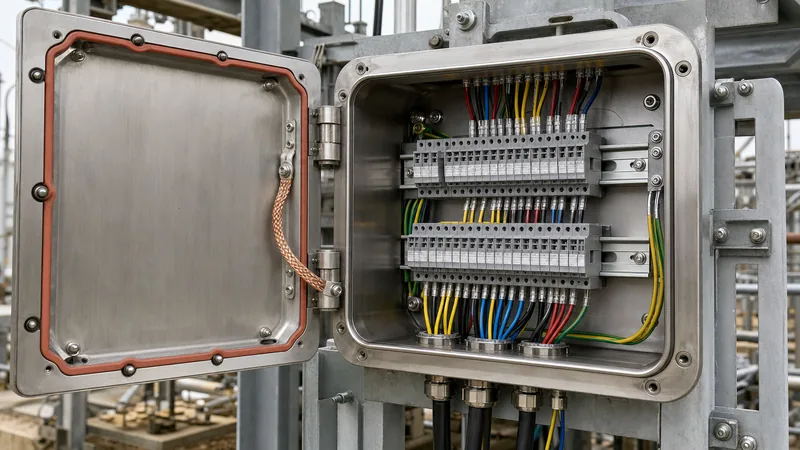
- An electrical junction box with cover protects conductor splices, marshalling terminals, and control taps against mechanical damage and environmental ingress.
- Metal electrical box with cover options fabricated from 316 stainless steel or cast aluminium provide IK10 mechanical impact protection and superior electromagnetic compatibility compared to polymer alternatives.
- Internal volumetric sizing must comply with NEC Article 314.16 or IEC 61439 spacing rules, reserving at least 20 to 25 percent spare terminal capacity for future field modifications.
- Outdoor ingress protection depends on continuous closed-cell silicone or polyurethane foam-in-place gaskets mated against precision knife-edge enclosure flanges.
- Factory testing of ingress-rated junction boxes requires verifying IP ratings under IEC 60529, earth-continuity path resistance under 0.1 ohms, and paint coating thickness per ISO 12944.
Quick answer: An electrical junction box with cover is an engineered enclosure designed to house, terminate, and protect electrical wiring joints, terminal blocks, and cable transitions from environmental contaminants, moisture, and accidental human contact. Selecting the correct model requires evaluating mechanical impact ratings (IK), ingress protection (IP/NEMA), internal conductor fill volume, and structural metallurgy.
In heavy industrial facilities, packaged substations, and utility switchyards, small balance-of-plant components frequently determine overall operational reliability. While primary attention focuses on medium-voltage breakers and distribution transformers, auxiliary wiring failures often trace back to compromised junction enclosures. A sub-standard enclosure allows moisture intrusion, promotes galvanic corrosion across terminal points, and compromises circuit integrity during fault conditions. System designers must treat every junction enclosure as a vital transition point governed by stringent physical and thermal performance criteria.
What Defines an Industrial Electrical Junction Box with Cover?
An industrial electrical junction box with cover serves as a protective enclosure designed specifically for branch circuit taps, conductor splicing, control-cable marshalling, and instrument isolation. Under standards such as IEC 62208 (empty enclosures for low-voltage switchgear and controlgear assemblies) and NFPA 70 (National Electrical Code / NEC Article 314), an enclosure must guarantee both mechanical protection and electrical safety throughout its design life.
Unlike light-duty domestic enclosures, an industrial electrical box with cover installed in an outdoor switchyard or industrial plant handles severe thermal cycles, corrosive atmospheres, and structural vibrations. The cover assembly is critical: it must maintain uniform sealing pressure against the box rim without warping over decades of service. High-integrity designs feature captive, corrosion-resistant machine screws or quick-release stainless steel draw latches. When deployed inside unit substation installations or alongside transformer marshalling racks, these enclosures isolate low-voltage instrument circuits, current transformer (CT) secondary leads, and control loops from primary medium-voltage transients.
Material Selection: Metal Electrical Box with Cover vs Polycarbonate
Selecting between metallic and polymer enclosures depends entirely on the operational environment, mechanical impact risks, and electromagnetic shielding requirements. A metal electrical box with cover provides the structural rigidity, thermal dissipation, and electromagnetic interference (EMI) attenuation necessary for heavy industrial and utility switchgear yards.
Fabricated mild steel with a durable thermoset powder-coat finish offers cost-effective mechanical defense in dry, indoor switchrooms. For harsh outdoor installations—such as coastal substations or chemical processing zones—grade 304 or marine-grade 316 stainless steel is mandatory to resist atmospheric pitting and chloride stress corrosion. Cast aluminium (such as AlSi12 alloy) delivers excellent thermal dissipation and structural rigidity while remaining lighter than steel. In contrast, non-metallic enclosures such as glass-reinforced polyester (GRP) or polycarbonate eliminate external corrosion concerns and remove the need for exterior enclosure grounding, as detailed in our comparative analysis on plastic electrical junction boxes. However, non-metallic options exhibit lower mechanical impact ratings (typically IK08) and provide no inherent high-frequency EMI shielding.
| Material Type | Tensile Yield Strength (MPa) | Mechanical Impact (IEC 62262) | Standard Ingress Rating | Thermal Conductivity (W/m·K) | Target Application |
|---|---|---|---|---|---|
| Mild Steel (Powder Coated) | 250 | IK10 | IP55 to IP66 | 50 | Indoor motor control, dry electrical vaults |
| 304 / 316 Stainless Steel | 290 | IK10 | IP66 to IP68 | 16 | Marine switchyards, outdoor chemical plants |
| Cast Aluminium (AlSi12) | 170 | IK09 / IK10 | IP66 / IP67 | 130 | Explosion-proof zones, high-heat locations |
| Glass-Reinforced Polyester (GRP) | 80 | IK08 / IK09 | IP66 | 0.25 | Highly acidic environments, coastal utility poles |
| Polycarbonate | 65 | IK08 | IP66 / IP67 | 0.20 | Solar PV arrays, instrumentation monitoring |
Sizing and Internal Volume Calculations under NEC Article 314
Enclosure sizing must follow exact volumetric rules to prevent conductor insulation damage, excessive internal thermal rise, and short circuits caused by physical crowding. According to NEC Article 314.16(B), every conductor, clamp, support fitting, and terminal block inside an electrical box with cover occupies a designated volume credit.
Consider a marshalling junction box designed to house ten terminal pairs connecting field instrument loops and secondary CT lines using 4 mm² (approximately 12 AWG) conductors:
- Determine Conductor Unit Volume: Under NEC Table 314.16(B), each 12 AWG conductor requires an internal volume allowance of 2.25 cubic inches (36.87 cm³).
- Count Conductor Equivalents: If the enclosure receives six incoming and six outgoing conductors, that equals 12 conductors. Add two volume allowances for internal ground conductors (bonding jumpers) and two volume allowances to account for internal DIN rail terminal hardware: 12 + 2 + 2 = 16 conductor equivalents.
- Calculate Required Minimum Free Space: 16 equivalents × 36.87 cm³ = 589.92 cm³ (36.0 in³).
- Factor Component Displacement and Thermal Margin: Terminal blocks, terminal separators, and field wire slack require an additional 100 percent clearance margin to allow for adequate wire-bending radius per NEC Table 312.6(A). The practical design volume becomes: 589.92 cm³ × 2.0 = 1,179.84 cm³ (72.0 in³).
- Physical Dimension Check: A standard enclosure measuring 200 mm × 150 mm × 120 mm provides an internal raw volume of 3,600 cm³ (219.6 in³), which easily accommodates the required 1,180 cm³, preserves bending space, and leaves over 30 percent spare capacity for future expansion.
Failure to compute proper internal volume results in damaged conductor sheaths during cover closure, pinch faults, and elevated temperature rise inside sealed IP66 assemblies.
Gasket Integrity and IP Ratings for an Outdoor Electrical Box with Cover
Outdoor electrical box performance depends directly on gasket longevity and mechanical flange design to prevent moisture and particulate ingress. An outdoor electrical junction box with cover intended for utility substation yards or industrial pads must meet a minimum rating of IP66 per IEC 60529 (or NEMA 4X per NEMA 250), ensuring absolute protection against dust penetration and powerful water jets.
Engineers must evaluate the gasket material against local ambient extremes:
- Continuous Polyurethane Foam-in-Place (FIP): Automated CNC-dispensed polyurethane gaskets provide an uninterrupted, jointless seal with exceptional memory retention across operating temperatures from -40°C to +80°C.
- Solid EPDM (Ethylene Propylene Diene Monomer): Highly resistant to ultraviolet degradation, ozone exposure, and water immersion; optimal for harsh outdoor substation environments.
- Expanded Closed-Cell Silicone: The industry standard for high-temperature or extreme cold zones (-60°C to +200°C), retaining structural elasticity without hardening or taking a permanent compression set.
Proper mechanical design incorporates an integrated drip shield or a formed knife-edge flange on the enclosure body. The knife edge concentrates cover-fastener torque into the center of the gasket, ensuring uniform compression without crushing the elastomer beyond its elastic limit. To understand enclosure seal engineering in greater detail, consult our comprehensive guide on electrical enclosures and ingress protection.
Earthing, Shielding, and Bonding Requirements
A metal electrical box with cover must establish continuous low-impedance equipotential bonding between the enclosure body, the removable cover, and the facility earthing grid to prevent dangerous touch voltages. Under IEC 61439-2 clause 8.4.3 and IEEE 80 switchyard grounding rules, all exposed conductive structural elements must bond reliably to the protective earth (PE) conductor.
Because powder coating and paint act as electrical insulators, metal-to-metal continuity cannot rely merely on mounting screws. High-grade enclosures include dedicated welded copper or brass earthing studs on both the interior base wall and the inside face of the cover. A flexible braided copper bonding strap—sized according to maximum upstream phase conductor cross-section (minimum 4 mm² or 10 AWG for control circuits)—must connect the cover stud to the main enclosure earth bar. When terminating shielded instrumentation cables, the enclosure must provide isolated shield busbars or spring-clamp grounding saddles to shunt electromagnetic interference to earth without introducing circulating ground loops, mirroring practices defined in our guide to outdoor terminal boxes.
Factory Inspection and Quality Checklist for Enclosures
Procuring junction enclosures for critical infrastructure requires strict factory quality surveillance before dispatch. Minor manufacturing flaws, such as porous welds or poor paint curing, lead to rapid degradation once installed in severe field conditions.
- Visual Weld and Seam Inspection: Verify that all continuous seams are laser-welded or TIG-welded without burn-through, spatter, or unsealed fissures. Grinding must leave edges smooth and free of burrs that could strip cable insulation.
- Coating Thickness and Cross-Hatch Adhesion: For powder-coated steel, verify dry film thickness (DFT) meets ISO 12944 specifications (typically ≥ 80 to 120 μm for severe industrial environments). Perform a cross-hatch tape adhesion test per ASTM D3359 to verify paint bonding integrity.
- Gasket Compression Verification: Apply water-soluble chalk to the enclosure rim, seal the cover to manufacturer-specified fastener torque, and remove it. The continuous chalk transfer confirms uniform gasket contact pressure along the entire perimeter.
- Earthing Continuity Resistance: Measure resistance between the external earth connection stud, the internal DIN rail, and any point on the painted cover using a calibrated micro-ohmmeter. Resistance must not exceed 0.1 ohms per IEC 61439-1 clause 10.5.2.
- Dimensional and Ingress Check: Confirm gland plate dimensions, knockout centerlines, and fastener thread pitch match approved construction drawings prior to packaging.
Next steps: specifying and sourcing
When preparing procurement packages or engineering specifications for an electrical junction box with cover, provide your suppliers with complete site parameters. Include design operating temperatures, required IP or NEMA ratings, chemical exposures, cable entry counts, and preferred gland plate materials. Our factory engineering team designs and manufactures certified low-voltage auxiliary cabinets, terminal enclosures, and marshalling solutions integrated directly with our prefabricated transformer substations and high-reliability HV/LV switchgear systems. Submit your technical drawings, one-line diagrams, and bill of materials through our dedicated quotation inquiry page to receive a factory-direct engineering review and competitive commercial proposal.
Frequently asked questions
What is the difference between a junction box and a terminal box?
A junction box primarily houses splices and taps between wire conductors, whereas a terminal box features organized DIN-rail terminal block assemblies for systematic control wiring and instrumentation marshalling.
Why is a metal electrical box with cover preferred over plastic in industrial substations?
Metal enclosures offer IK10 mechanical impact protection, inherent electromagnetic shielding against switchyard high-frequency transients, and continuous low-resistance bonding required by utility safety codes.
What IP rating is required for an outdoor electrical junction box with cover?
A minimum rating of IP66 is recommended for outdoor industrial installations, ensuring complete defense against windblown dust and high-pressure water jets from any angle.
How do you calculate wire fill capacity for an electrical box with cover?
Calculate total volume credits per conductor, clamp, and fitting under NEC Article 314.16(B), then select an enclosure whose internal volumetric capacity exceeds this sum plus an operational wire-bending allowance.
Do you need an earthing strap between the box and its cover?
Yes, metallic covers must be bonded to the main enclosure earth stud via a dedicated flexible braided copper strap to prevent electric shock hazards if an energized conductor touches the cover.
Can you drill custom cable entry holes into an ingress-rated junction box?
Yes, but penetrations must use punch dies rather than twist drills to maintain roundness, and cable glands must carry an equal or higher IP rating with suitable sealing washers.
Tags: electrical junction box with cover electrical box with cover metal electrical box with cover switchgear enclosures substation auxiliary wiring


