Key takeaways
- A grounding grid dissipates high-magnitude fault currents directly into the earth to maintain step and touch voltages below human physiological fibrillation thresholds.
- IEEE 80-2013 Clause 11.3 and IEC 61936-1 establish strict conductor sizing equations based on symmetrical fault currents, fault clearing duration, and conductor material constants.
- A target earth resistance below 1.0 ohm is standard for medium- and high-voltage utility substations, preventing excessive ground potential rise during phase-to-earth faults.
- Exothermic welding provides irreversible, low-resistance connections that resist galvanic corrosion far better than mechanical bolted clamps within subterranean earthing systems.
- Renewable collector substations require unified ground grids that integrate solar array structures, battery enclosures, and medium-voltage switchgear to prevent circulating stray currents.
Quick answer: A grounding grid is an interconnected network of buried horizontal conductors and vertical ground rods engineered to safely dissipate short-circuit currents into the earth. It limits surface potential gradients, preventing lethal touch and step voltages for personnel while protecting medium- and high-voltage substation equipment.
In high-voltage electrical installations, phase-to-ground faults unleash thousands of amperes into the surrounding earth. Without an engineered grounding grid, this current creates hazardous voltage differentials across the ground surface, known as ground potential rise (GPR). Whether deploying modular switchgear or interconnecting renewable power plants, establishing a low-impedance earthing interface is an uncompromising life-safety and operational prerequisite.
Modern utility interfaces demand stringent verification of earthing parameters to ensure compliance with standards like IEEE 80 and IEC 61936-1. As distributed generation and commercial energy storage continue to expand, understanding the interaction between collector networks and a utility-grade grid integration of renewable energy sources requires precise calculation, careful material selection, and rigorous soil testing.
Principles of Ground Grid Design in Substation Applications
Substation earthing systems must maintain prospective touch and step potentials well below the maximum tolerable thresholds established for human ventricular fibrillation. When a single line-to-ground fault occurs on an incoming line or within power equipment, the fault current passes through the earth return path back to the system neutral. A high-integrity grounding grid substation installation controls the distribution of this returning current.
Tolerable voltage thresholds depend heavily on fault clearing time and the body weight assumption specified in the project engineering standard. Per IEEE 80-2013 Clause 8.3, the tolerable touch voltage ($E_{touch}$) for a person weighing 70 kg standing on a crushed-rock surface layer is calculated as:
$$E_{touch70} = (1000 + 1.5 C_s \rho_s) \times \frac{0.157}{\sqrt{t_s}}$$
Where $\rho_s$ represents the resistivity of the surface layer (typically 2,000 to 3,000 $\Omega\cdot\text{m}$ for washed granite aggregate), $C_s$ is the surface derating factor based on layer thickness, and $t_s$ is the primary protection clearing duration in seconds. If the mesh voltage calculated within the grid bays exceeds this tolerable boundary, high-voltage flashover or fatal shocks can occur during an earth fault.
In utility-scale installations, an engineered ground grid design balances conductor density against excavation costs. Conductors are typically laid out in a grid mesh with perimeter loops extending 1 metre beyond the security fence line. This perimeter ring neutralises the steep potential gradient near metal boundaries, ensuring that personnel operating exterior gates or fence lines are not exposed to transferred touch potentials.
Sizing Calculations and Worked Example per IEEE 80
Conductor cross-sectional area sizing ensures that the subterranean conductor does not fuse or anneal under maximum asymmetrical fault conditions. IEEE 80-2013 Clause 11.3 provides the formula for thermal capacity of conductors subjected to short-duration fault currents:
$$A_{mm^2} = I \times \frac{1}{\sqrt{\left( \frac{TCAP \times 10^{-4}}{t_c \alpha_r \rho_r} \right) \ln \left( \frac{K_0 + T_m}{K_0 + T_a} \right)}}$$
Consider an engineering scenario for a 33 kV / 132 kV renewable collector substation. The system parameters are defined as follows:
- Symmetrical earth-fault current ($I_f$): 25 kA
- Fault duration ($t_c$): 0.5 s
- Conductor material: Soft-drawn annealed copper (100% IACS conductivity)
- Maximum allowable temperature ($T_m$): 1083 °C (exothermic welded joints)
- Ambient earth temperature ($T_a$): 30 °C
- Material constants: $K_0 = 234$, $TCAP = 3.42\text{ J}/(\text{cm}^3\cdot^\circ\text{C})$, $\alpha_r = 0.00393$, $\rho_r = 1.724\ \mu\Omega\cdot\text{cm}$
Using the simplified material factor $K_f = 7.01$ for annealed copper with exothermic connections, the calculation yields:
$$A_{mm^2} = I_f \times K_f \times \sqrt{t_c} = 25 \times 7.01 \times \sqrt{0.5} = 123.92\text{ mm}^2$$
Because standard conductor sizing specifies nearest commercial gauges, the design selects a $150\text{ mm}^2$ stranded bare copper conductor (or standard 250 kcmil conductor at $126.7\text{ mm}^2$), providing a thermal safety margin exceeding 20%.
Next, the Sverak equation (IEEE 80 Clause 14.2) determines the approximate substation ground resistance ($R_g$) for a square grid area of 2,500 $\text{m}^2$ ($50\text{ m} \times 50\text{ m}$), with uniform soil resistivity $\rho = 80\ \Omega\cdot\text{m}$, burial depth $h = 0.8\text{ m}$, and total buried conductor length $L_T = 1,400\text{ m}$:
$$R_g = \rho \left[ \frac{1}{L_T} + \frac{1}{\sqrt{20 A}} \left( 1 + \frac{1}{1 + h \sqrt{20 / A}} \right) \right]$$
Substituting the values:
$$R_g = 80 \left[ \frac{1}{1400} + \frac{1}{\sqrt{50000}} \left( 1 + \frac{1}{1 + 0.8 \sqrt{20 / 2500}} \right) \right] \approx 0.73\ \Omega$$
The calculated resistance of 0.73 $\Omega$ successfully satisfies the typical utility interconnection requirement of $R_g \le 1.0\ \Omega$, preventing excessive GPR during phase-to-ground faults.
Conductor Materials and Grid Earthing System Architectures
Selecting the correct metallurgy for an earthing grid governs its operational longevity, current-carrying performance, and resistance to subterranean corrosion. Engineers must evaluate chemical soil properties, soil pH, moisture content, and the presence of dissolved salts when finalising conductor specifications.
| Material Type | Electrical Conductivity (% IACS) | Tensile Strength (MPa) | Corrosion Resistance | Relative Material Cost | Standard Compliance |
|---|---|---|---|---|---|
| Annealed Bare Copper | 100% | 200 - 250 | Excellent in neutral/acidic soils; poor in high sulphur | High (1.0x baseline) | IEEE 80, IEC 62561-2 |
| Copper-Clad Steel (CCS, 40%) | 40% | 500 - 850 | High (impervious copper skin protects steel core) | Moderate (0.6x baseline) | ASTM B228, IEEE 80 |
| Galvanised Mild Steel | 8 - 12% | 350 - 500 | Fair; zinc depletes rapidly in soils below pH 6.0 | Low (0.3x baseline) | BS 7430, IEC 61936-1 |
| Stainless Steel (316L) | 2 - 3% | 500 - 700 | Superior in marine and hypersaline environments | High (1.2x baseline) | IEC 62561-2 |
While bare annealed copper provides superior ampacity per cross-section, Copper-Clad Steel (CCS) has emerged as an attractive alternative in areas prone to copper theft. CCS delivers exceptional tensile strength for machine-driven vertical earthing rods while maintaining galvanic compatibility with standard exothermic weld cartridges.
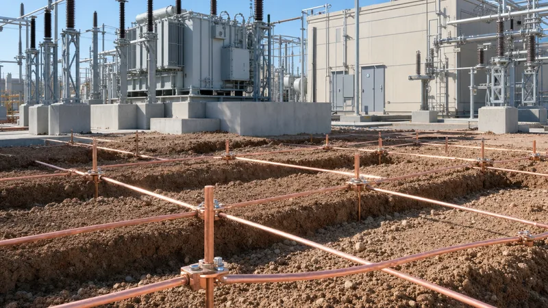
Every complete grid earthing system architecture features perimeter ring loops, cross-connecting internal conductors, and vertical driven rods. Driven rods are placed at grid corners and near lightning arresters, power transformer neutrals, and high-voltage circuit breaker positions. These locations absorb the high-frequency wavefronts of lightning surges and direct them into deeper, lower-resistivity geological strata.
Step-by-Step Installation and Soil Testing Procedures
Installing a substation earthing network demands disciplined earthwork execution, rigorous conductor jointing, and precise post-installation testing per IEEE 81. Deviations during trenching or backfilling can introduce void pockets that elevate grid impedance and compromise safety margins.
- Perform soil resistivity testing: Measure apparent soil resistivity across the substation footprint using the Wenner four-pin method (IEEE 81 Clause 5). Take multi-depth pin spacings (1 m, 2 m, 4 m, 8 m, 16 m) along perpendicular transects to generate an accurate two-layer geological soil model.
- Excavate trench networks: Excavate conductor trenches to the specified engineering depth (typically 0.6 m to 1.0 m below final grade level). Ensure the trench base is clear of sharp rocks, debris, or organic matter that could damage conductor strands.
- Drive vertical earth electrodes: Install copper-bonded steel rods at grid perimeter nodes and apparatus positions using hydraulic or pneumatic driving heads. Couple rod segments with bronze threaded couplers or exothermic joints to prevent thread stripping.
- Lay and weld grid conductors: Lay stranded conductor along the trench runs, securing connections with exothermic weld moulds. Clean all conductor mating ends to bright metal with a wire brush, preheat moulds if moisture is present, and reject welds showing excessive porosity or slag inclusions.
- Backfill with engineered soil: Backfill the trench using sieved native soil free of aggregate. Apply conductive ground-enhancing backfills (bentonite clay or carbonaceous backfill) in rocky strata where soil resistivity exceeds 300 $\Omega\cdot\text{m}$. Compact in 150 mm lifts.
- Execute Fall-of-Potential verification: After backfilling is complete, measure the total grid resistance using the Fall-of-Potential method per IEEE 81 Clause 8.2. Place the current probe ($C_2$) at a distance of at least 5 times the maximum grid diagonal dimension ($D$), and move the potential probe ($P_2$) through the 61.8% position to generate the resistance flat curve.
Field commissioning teams must log all test curves to establish baseline impedance values before equipment energisation, as outlined in our comprehensive substation testing guide.
Substation Grounding Grid Integration for Renewable Energy Systems
Utility-scale solar, wind collector arrays, and battery energy storage systems (BESS) require integrated earthing schemes that bridge the substation yard and distributed generation units. Medium-voltage collector circuits create extended capacitive networks, meaning ground faults generate transient overvoltages if earthing meshes are isolated from one another.
When connecting integrated skids such as a prefabricated transformer substation or medium-voltage equipment, bond the internal equipment ground bus directly to the subterranean grid using at least two independent copper conductor risers placed at diagonally opposite corners. This redundant connection provides dual return paths, ensuring equipment cases remain safely clamped to local ground potential even if one connection experiences physical severance.
In photovoltaic plants, each tracker string or mounting structure must maintain equipotential bonding with the central collector substation grid. Without this unified equipotential bonding plane, lighting strikes on the solar field can drive surge currents back into the medium-voltage switchgear ground bus. This can result in insulation breakdown within equipment like HV and LV switchgear assemblies or trip sensitive digital protective relays, as detailed in our guide to substation protection schemes.
For installations deploying integrated unitised infrastructure, referencing the layout guidelines in our unit substation engineering guide ensures structural steelwork, transformer tank earthing, and lightning down-conductors bond seamlessly into the main earth mat without forming ground loops.
Next steps: specifying and sourcing
Specifying a heavy-duty substation earthing system requires complete project parameters: calculated symmetrical fault levels (kA), fault clearing times (seconds), geodetic soil resistivity surveys, and layout drawings detailing perimeter boundaries. Ensure your procurement documentation specifies conductor sizing per IEEE 80 or IEC 61936-1, connector types (exothermic vs compression), and crushed-rock surface characteristics.
Our engineering team designs and manufactures utility-grade distribution and power equipment, offering fully certified packaged transformer substations and switchgear assemblies tailored to severe fault duties. Explore our engineered transformer substations and high-reliability switchgear lineups, or submit your single-line diagrams directly through our quotation request page. For detailed technical evaluations, contact our engineering office directly at our contact page.
Frequently asked questions
What is the primary purpose of a grounding grid in a substation?
A grounding grid dissipates high-magnitude earth fault currents into the ground to protect personnel and apparatus. It maintains surface step and touch potentials below human fibrillation limits and clamps equipment frames to a stable reference voltage.
What is the difference between touch voltage and step voltage?
Touch voltage is the potential difference between a grounded metallic structure and a person's hand during a fault. Step voltage is the potential difference between a person's feet spaced one metre apart on the substation ground surface without contacting any metallic object.
What is a safe resistance value for a substation grounding grid?
Most utility distribution and transmission substations require an earth grid resistance of 1.0 ohm or less. In very large extra-high-voltage (EHV) substations, target values frequently drop below 0.5 ohms to limit ground potential rise during high-magnitude short circuits.
Why is crushed rock spread on the surface of a substation switchyard?
Crushed rock provides a high-resistivity surface buffer layer (typically 2,000 to 3,000 ohm-metres) over the natural soil. This layer adds contact resistance beneath a person's feet, substantially raising the tolerable touch and step voltage limits under fault conditions.
Can copper-clad steel replace pure copper in grounding grid design?
Yes, copper-clad steel (CCS) is widely accepted under IEEE 80 standards for substation earthing. It combines the corrosion resistance of an external copper metallurgical barrier with the high tensile strength and anti-theft properties of a carbon steel core.
Tags: grounding grid grounding grid substation ground grid design earthing grid grid earthing system


