Key takeaways
- Distributed energy resources (DER) are decentralised electricity generation or storage units connected directly to the local distribution network or behind the customer meter.
- Reverse power flow from distributed generation alters traditional radial feeder voltage profiles, requiring distribution transformers with coordinated on-load tap changers and bi-directional protection schemes.
- IEEE 1547-2018 clause 5 mandates specific voltage and frequency ride-through capabilities for all grid-connected distributed energy systems.
- Transformer impedance must be carefully matched to prevent excessive local voltage rise, calculated via the simplified formula Delta V approximately equals (R * P + X * Q) / V.
- Integrating battery energy storage alongside distributed renewable energy mitigates local intermittency and provides essential synthetic inertia to the distributed power grid.
Quick answer: Distributed energy resources (DER) are decentralised, small-to-medium-scale electricity generation or storage assets connected to the local medium-voltage or low-voltage distribution network, rather than the bulk transmission system. Common installations range from 10 kW rooftop solar up to 20 MW utility battery systems, fundamentally altering power flows from unidirectional to bidirectional.
Historically, the electrical grid operated on a straightforward centralised model: massive power stations generated electricity at high voltages, transmitted bulk energy across long distances, and delivered it downward to passive end-users through radial distribution networks. The widespread adoption of der energy has transformed this passive framework into an active, bi-directional distributed power grid. Today, EPC contractors, utility engineers, and system designers must grapple with complex distribution challenges, including thermal overloading, bidirectional short-circuit currents, and harmonic injection. Successfully integrating these assets requires a deep understanding of distribution equipment specifications, particularly regarding step-up transformers, switchgear ratings, and grid compliance standards such as IEEE 1547 and IEC 61000.
What is Distributed Generation and How Does It Define DER?
The definition of distributed energy resources encompasses physical assets located close to the point of consumption that can generate, store, or actively manage electricity. To answer the common query of what is distributed generation: it refers specifically to the generation component of DER, producing power locally rather than relying exclusively on centralised thermal, hydro, or nuclear plants. The broader term der distributed energy resources includes both generation assets and controllable loads, such as battery energy storage systems (BESS), electric vehicle supply equipment (EVSE), and demand-response infrastructure.
When engineers evaluate what is distributed power generation within modern industrial networks, the distinction rests on the point of common coupling (PCC). While central stations interface at transmission voltages from 110 kV to 765 kV, distributed electricity generation typically connects to distribution feeders operating between 400 V and 36 kV. To fully grasp the distributed generation meaning, one must view these assets as active nodes within the distribution network. A comprehensive architectural diagram of a distributed energy resources diagram reveals rooftop photovoltaics, ground-mounted solar farms, microturbines, and commercial battery storage units running through dedicated step-up transformers directly into local distribution substations, governed by our comprehensive guide on grid integration of renewable energy sources.
Primary Distributed Energy Resources Examples and Technology Types
Modern distributed energy resources examples span diverse prime movers and chemical storage technologies, each presenting unique operating characteristics to distribution network operators (DNOs). Classifying these assets requires evaluating their dispatchability, rotational inertia, and power electronics interfaces.
- Distributed generation solar: Photovoltaic (PV) installations ranging from residential strings (5 to 15 kW) to commercial rooftops (100 to 1,000 kW) and small ground-mount utility systems (1 to 10 MW). These systems are non-dispatchable and connect via solid-state inverters.
- Battery Energy Storage Systems (BESS): Lithium iron phosphate (LFP) containers paired with bi-directional inverters. Working through a dedicated power conversion system, storage provides rapid frequency response, peak shifting, and capacity firming.
- Distributed wind generation: Small-to-medium wind turbines (50 kW to 2 MW) tied to local 11 kV or 33 kV feeders, exhibiting variable power output driven by local weather patterns.
- Reciprocating combined heat and power (CHP): Natural gas or biogas-fuelled internal combustion engines (250 kVA to 5 MVA) supplying synchronous generation alongside industrial thermal processes.
- Fuel cells and microturbines: Low-inertia or static electrochemical sources capable of continuous base-load generation with ultra-low harmonic distortion.
Engineering Challenges in the Distributed Power Grid
Operating a distributed power grid creates serious technical hurdles because classic distribution infrastructure was engineered solely for top-down, unidirectional current. When local distributed energy production exceeds immediate feeder demand, reverse power flow occurs, causing feeder voltage to rise toward the load terminals.
In standard radial topologies—as detailed in our analysis of radial feed vs loop feed networks—the substation maintains the highest voltage, which drops steadily along the feeder length due to line impedance. Distributed generation systems invert this gradient. If generation exceeds consumption, current flows backward into the medium-voltage substation, triggering overvoltage conditions that breach the statutory limits outlined in EN 50160 (typically nominal voltage plus or minus 10%). Furthermore, fault current contributions from inverter-based resources differ dramatically from rotating machines. Synchronous generators contribute 5 to 7 times full-load current (FLC) under bolted three-phase faults, whereas inverter-coupled distributed renewable energy units contribute only 1.1 to 1.5 times FLC due to software current-limiting algorithms, frequently desensitising legacy overcurrent relays.
Transformer Selection and Engineering for DER Interconnection
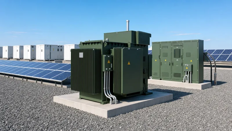
Selecting transformers for distributed power system integration requires accounting for cyclic thermal stresses, bidirectional flux, harmonic currents, and neutral grounding arrangements. Interconnection step-up units must withstand prolonged periods of high load during peak generation hours, often running in reverse from low-voltage inverters to medium-voltage collector systems.
Engineers must evaluate core losses and harmonic derating per IEEE C57.110. Inverter switching frequencies generate high-frequency current harmonics that induce eddy current losses in winding conductors and structural steel. Specifying an appropriate K-factor (typically K-4 to K-9 for modern solar inverters) or purchasing low-loss pad-mounted transformers prevents premature insulation degradation. Furthermore, vector groups must be selected with care: a Dyn11 or YNd11 configuration is standard to isolate third-order triplen harmonics from propagating into the utility network, while offering a stable ground reference for distribution ground-fault protection.
| DER Interconnection Parameter | Standard Distribution Unit | DER Dedicated Step-Up Unit | Engineering Significance |
|---|---|---|---|
| Power Flow Capability | Unidirectional (HV to LV) | Bidirectional (LV to HV / HV to LV) | Core saturation and stray flux control under reverse power |
| Impedance Tolerance (%Z) | Standard (+/- 10% per IEC 60076-1) | Tight (+/- 5% or 7.5% per IEEE C57.12.00) | Limits local voltage rise and fault current levels |
| Harmonic Spectrum Capability | THDi < 2% (linear loads) | THDi up to 5% with elevated high-frequency components | Demands electrostatic shielding and low-loss winding designs |
| Tap Changer Configuration | De-energised Tap Changer (DETC, +/- 2x2.5%) | On-Load Tap Changer (OLTC) with bidirectional sensing | Regulates dynamic feeder voltage swings in real time |
| Thermal Insulation Class | Class A (105 deg C, 65 deg C rise) | Class F (155 deg C) or hybrid Class H insulation | Accommodates thermal cycling and peak ambient solar irradiance |
Worked Calculation: Feeder Voltage Rise from Distributed Generation Solar
A critical task when specifying transformers and interconnections for distributed generation solar is verifying that point of common coupling voltage rise remains within utility tolerances. Consider an industrial facility adding a 2,000 kW (2.0 MW) solar PV array tied to an 11 kV feeder via an on-site step-up distribution transformer.
We use the standard simplified voltage rise approximation formula:
Delta V approx (R * P + X * Q) / V_nom
- Grid Nominal Line Voltage (V_nom): 11,000 V (11 kV line-to-line)
- Active Power injected by solar array (P): 2,000 kW (2,000,000 W)
- Reactive Power injected / absorbed (Q): 0 kvar (operating at unity power factor, cos phi = 1.0)
- Feeder cable resistance (R): 0.45 Ohms
- Feeder cable inductive reactance (X): 0.25 Ohms
- Transformer Impedance: 2,500 kVA, Z = 6.0%, X/R ratio = 4.5
Step 1: Calculate the line-to-line voltage rise across the distribution feeder alone:
Delta V_feeder = (0.45 Ohms * 2,000,000 W + 0.25 Ohms * 0 Var) / 11,000 V = 900,000 / 11,000 = 81.82 V (line-to-neutral equivalent: 81.82 / sqrt(3) = 47.24 V).
Expressed as a percentage of nominal 11 kV line-to-line voltage: (81.82 V / 11,000 V) * 100 = 0.74%.
Step 2: Add transformer impedance voltage drop/rise under full reverse generation:
Base impedance Z_base = (V_nom^2) / S_base = (11,000^2) / 2,500,000 = 48.4 Ohms.
Transformer equivalent impedance Z_tx = 0.06 * 48.4 Ohms = 2.904 Ohms. With an X/R ratio of 4.5, R_tx = 2.904 / sqrt(1 + 4.5^2) = 0.63 Ohms.
Voltage rise across the transformer: Delta V_tx = (0.63 Ohms * 2,000,000 W) / 11,000 V = 114.55 V (1.04% of nominal).
Step 3: Evaluate total voltage rise at low-voltage busbar: Total rise = 0.74% + 1.04% = 1.78%. Because 1.78% is well below the statutory utility limit of 3.0% maximum voltage variation for an individual installation under IEEE 1547-2018 Clause 5.2, this configuration prevents overvoltage tripping without requiring active reactive power absorption (Q control) from the inverter.
Grid Interconnection Standards: IEEE 1547 and IEC 60076 Compliance
Compliance with international standards ensures that distributed energy systems integrate reliably without compromising grid security. IEEE 1547-2018 represents the benchmark standard for interconnecting distributed electricity sources with electric power systems.
- Voltage Regulation and Reactive Power Control: IEEE 1547-2018 Clause 5 mandates that DER must possess adjustable reactive power capabilities. Systems must support reactive power modes including constant power factor, voltage-reactive power (Volt-VAr), and active-reactive power (Watt-VAr) curves to counteract the voltage rise calculated above.
- Abnormal Grid Ride-Through: Under Clause 6, DER units cannot instantly trip off-line during temporary grid disturbances. Category II and III devices must maintain stability during wide voltage excursions (down to 0.5 per unit) and frequency shifts (47.0 Hz to 62.0 Hz) to avoid cascading grid collapse.
- Anti-Islanding Protection: Unintentional islanding occurs when a DER continues to energise a de-energised utility feeder section, posing severe life-safety risks to maintenance crews. Relays must detect loss of grid supply via active frequency drift or passive ROCOF (rate of change of frequency) sensors and disconnect within 2.0 seconds per IEEE 1547 Clause 8.
- Transformer and Equipment Design: Power transformers handling DER feeds must comply with IEC 60076-1 regarding thermal rise under unbalanced loads, while switchgear should comply with IEC 62271-200. Where voltage fluctuations are continuous, integrating an active voltage regulator or deploying transformers featuring a modern load tap changer provides essential dynamic voltage control.
Technical Benefits of Distributed Energy Resources in Modern Power Systems
The technical benefits of distributed energy resources extend far beyond basic decarbonisation. When correctly located and controlled through automated microgrid controllers or distribution management systems (DERMS), these assets substantially improve network resilience and efficiency.
By generating power at or near the load centre, distributed energy dramatically reduces I^2 * R ohmic transmission losses, which historically account for 6% to 8% of total generated energy on central grids. Furthermore, der distributed energy resources provide non-wires alternatives (NWA) for utilities. Rather than upgrading expensive transmission corridors and replacing high-capacity thermal transformers, utilities deploy localized battery storage and solar arrays to clip peak demands. This capital deferral extends asset life across aging urban substations. When coupled with advanced automated switchgear, islandable DER clusters create self-healing microgrids that supply critical facilities—such as hospitals, data centres, and water treatment plants—during prolonged transmission system outages.
Next Steps: Specifying and Sourcing DER Transformers and Equipment
To specify robust distribution transformers, substations, and medium-voltage switchgear for your next distributed energy resources project, precise technical documentation is paramount. Prepare your single-line diagram (SLD), total rated inverter capacity (kVA and kW), expected harmonic profile (THDi), required vector group (e.g., Dyn11), and utility-mandated primary/secondary voltage levels. Our factory engineering team specializes in tailoring low-loss transformer substations and high-efficiency oil-immersed transformers built specifically for continuous bidirectional duty, strict short-circuit withstand, and IEEE/IEC compliance. For detailed equipment selections, technical reviews, or project tenders, submit your requirements via our transformer quotation page or speak with our technical team directly on our contact page.
Frequently asked questions
what is distributed generation
Distributed generation is the production of electricity from small-to-medium systems located close to the point of consumption, connected to the local distribution network rather than centralised transmission grids. Common examples include rooftop solar, industrial combined heat and power systems, and community wind turbines.
what is distributed power generation
Distributed power generation refers to decentralised electrical power production systems located across industrial, commercial, or residential sites. Unlike centralised thermal or hydro stations generating hundreds of megawatts, distributed power generation installations typically range from several kilowatts to tens of megawatts, feeding power directly into medium- or low-voltage networks.
what is distributed power
Distributed power is electrical energy generated, stored, and managed locally across decentralised network nodes rather than delivered from a distant, centralised power plant. It combines distributed energy generation assets with local storage and intelligent load management to supply consumers reliably and reduce reliance on long-distance transmission grids.
define distributed energy resources
Distributed energy resources (DER) are defined as small-to-medium-scale generation, energy storage, and controllable electrical loads directly interconnected with local distribution systems or positioned behind customer utility meters. They include solar arrays, battery storage, microturbines, fuel cells, and demand-response assets that actively influence power flows.
What causes voltage rise with distributed generation solar?
Voltage rise occurs when distributed generation solar injects active power into a distribution feeder that exceeds immediate local demand. This forces current to flow backward toward the substation across line and transformer impedance, creating a positive voltage gradient that raises the voltage at the point of common coupling.
Why do transformers for DER applications need specific design considerations?
Transformers serving DER applications must withstand bidirectional power flow, elevated harmonic currents injected by solid-state inverters, and thermal cycling from intermittent generation. They require low stray load loss, tailored impedance to regulate voltage, and electrostatic shields to mitigate capacitive high-frequency transfer.
Tags: distributed energy resources distributed generation distributed power grid der energy renewable energy


