Key takeaways
- Air insulated switchgear relies on ambient atmospheric air as the primary dielectric medium, supplemented by solid epoxy or composite barriers for phase-to-phase and phase-to-earth insulation.
- Per IEC 62271-200, modern medium-voltage air insulated switchgear utilizes Loss of Service Continuity class LSC2B with metallic partitions (PM) to permit maintenance in the breaker compartment while busbars remain energised.
- Minimum phase-to-phase and phase-to-earth electrical clearances in atmospheric air are strictly governed by Basic Impulse Level (BIL) ratings, requiring at least 125 mm for 12 kV (75 kV BIL) and 280 mm for 36 kV (170 kV BIL) per standard ambient conditions.
- Air switchgear offers significantly lower initial capital expenditure and simpler civil infrastructure requirements than gas-insulated alternatives, eliminating SF6 gas handling, monitoring, and future regulatory phase-out liabilities.
- Internal Arc Classification (IAC) ratings such as AFLR 31.5 kA for 1 second verify operator safety by containing thermal and pressure blast energy through dedicated exhaust plenums and mechanical interlocks.
Quick answer: Air insulated switchgear is an electrical distribution assembly where primary electrical conductors and interrupting devices utilize atmospheric air as the main phase-to-phase and phase-to-earth dielectric medium, isolated inside compartmentalised metal enclosures up to 40.5 kV.
In electrical power networks, air insulated switchgear (AIS) remains the global benchmark for primary and secondary medium-voltage power distribution in utility substations, industrial plants, and generation facilities. Unlike enclosed gas or liquid systems, atmospheric air provides an abundant, cost-free, and environmentally benign insulating medium. However, because ambient air possesses a lower dielectric breakdown strength than compressed gases, AIS architecture requires precise phase spacing, engineered solid dielectric barriers, and controlled indoor environmental conditions.
Specifying medium-voltage AIS requires balancing system fault levels, insulation coordination under atmospheric variations, structural arc containment, and operational availability. Design engineers must evaluate structural partitioning classifications under IEC 62271-200 or IEEE C37.20.2, verify creepage distances across bus support insulators, and size pressure relief venting to prevent catastrophic enclosure rupture during an internal fault. Understanding these mechanical and electrical parameters ensures the switchgear delivers safe, maintainable, and reliable service over a 30- to 40-year design life.
What Is Air Insulated Switchgear and How Does It Work?
Air insulated switchgear is a factory-assembled metal enclosure housing switching equipment where primary circuit conductors are surrounded by ambient atmospheric air to prevent electrical flashover. The primary switching device—typically a withdrawable vacuum circuit breaker—interrupts normal load currents and fault currents inside sealed vacuum interrupters, while the surrounding busbar, cable terminations, and instrument transformers rely on air clearances and solid insulation materials such as cast cycloaliphatic epoxy resin.
Air switchgear functions by compartmentalising distinct power stages into segregated, grounded metallic cells. When the circuit breaker closes, continuous load current flows from the main copper busbars through tulip-style primary disconnect clusters, traverses the vacuum interrupter contacts, passes through current transformers, and exits through the medium-voltage cable terminations to the outgoing load. During a downstream short circuit, protection relays detect the overcurrent condition via current transformers, energising the breaker's trip coil to separate the vacuum contacts within 30 to 60 milliseconds.
The air surrounding the primary conductors must withstand both continuous power frequency operating voltages and transient overvoltages caused by lightning strikes or network switching operations. Because atmospheric pressure air has a dielectric breakdown strength of approximately 3 kV per millimetre under uniform field conditions, AIS utilizes substantial mechanical spacing alongside shaped insulating barriers to manage electric field gradients. Engineers integrating system components can evaluate operational parameters within our electrical switchgear guide and examine interrupter mechanics in our detailed vacuum circuit breaker guide.
Air Insulated Switchgear Architecture and Compartment Design
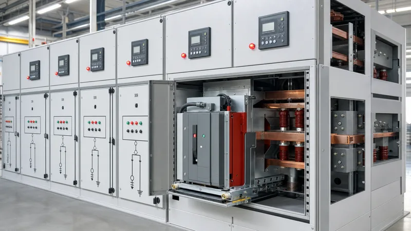
Modern medium-voltage air insulated switchgear is designed around four segregated, grounded metallic compartments to maximize operational safety and service continuity during maintenance. Standardized under IEC 62271-200 as Loss of Service Continuity category LSC2B with Partition Class PM (metallic), this architectural arrangement ensures that accessing one compartment leaves adjacent functional units and busbars completely operational.
The standard four-compartment architecture comprises:
- Busbar Compartment: Houses the main three-phase flat or profiled electrolytic copper busbar system. The conductors run horizontally through the switchboard line-up, supported by track-resistant epoxy insulators and passing through partition bushings between adjacent panels to stop inter-cubicle arc propagation.
- Circuit Breaker Compartment: Accommodates the withdrawable switching device mounted on a roll-in cassette. Mechanical guide rails, racking spindles, and position micro-switches ensure precise alignment of primary disconnect spouts. Automatic metallic safety shutters close and ground mechanically over the stationary contact spouts whenever the circuit breaker moves from the 'Connected' position to the 'Test' or 'Disconnected' position.
- Cable and Instrument Transformer Compartment: Provides termination pads for single-core or three-core medium-voltage cables, window-type or cast-resin current transformers (CTs), inductive voltage transformers (VTs), and surge arresters. It features generous floor clearance for cable gland plates and zero-sequence core-balance CTs.
- Low-Voltage Control Compartment: Completely segregated from all primary medium-voltage circuits, this top-mounted metal cabinet houses microprocessor-based protection relays, metering units, terminal blocks, trip circuit supervision modules, auxiliary relays, and automation programmable logic controllers (PLCs).
For high-reliability configurations, review structural criteria in the metal-clad switchgear guide, where grounded metal barriers isolate all live components into discrete fire- and arc-resistant zones.
Technical Ratings, Clearances and Dielectric Sizing
Dielectric sizing for air insulated switchgear is determined by electrical clearances through air and creepage distances across solid insulating surfaces, calculated according to the system's rated voltage and Basic Impulse Level (BIL). Because ambient air density, humidity, and atmospheric pressure directly affect breakdown voltage, clearances must satisfy dielectric test voltages specified in IEC 60071-1 and IEC 62271-1 clause 6.2.
The minimum phase-to-phase and phase-to-earth clearances in dry, clean atmospheric air under standard atmospheric conditions (temperature 20 °C, pressure 101.3 kPa, absolute humidity 11 g/m³) follow strict engineering design thresholds:
| Rated Voltage (kV) | Rated Power Frequency Withstand (kV rms) | Rated Lightning Impulse / BIL (kV peak) | Minimum Air Clearance Phase-to-Earth (mm) | Minimum Air Clearance Phase-to-Phase (mm) | Minimum Creepage Distance (mm/kV) |
|---|---|---|---|---|---|
| 7.2 | 20 | 60 | 90 | 105 | 20 to 25 |
| 12.0 | 28 | 75 | 125 | 145 | 20 to 25 |
| 17.5 | 38 | 95 | 160 | 185 | 25 |
| 24.0 | 50 | 125 | 210 | 235 | 25 to 31.5 |
| 36.0 | 70 | 170 | 280 | 320 | 31.5 |
| 40.5 | 85 / 95 | 185 / 200 | 320 | 360 | 31.5 |
Where switchgear is installed at altitudes exceeding 1,000 metres above sea level, atmospheric density decreases, reducing the dielectric strength of air. IEC 62271-1 clause 2.2.1 defines an altitude correction factor (Ka) applied to external insulation:
Ka = e^(m * (H - 1000) / 8150)
For an installation at an altitude H = 2,500 metres with an exponent m = 1 (for lightning impulse voltage at minimum clearance):
Ka = e^(1 * (2500 - 1000) / 8150) = e^(1500 / 8150) = e^0.184 = 1.202
A 24 kV rated system requiring a sea-level BIL of 125 kV must be engineered to withstand an impulse test voltage of 125 kV * 1.202 = 150.3 kV. Consequently, the switchgear enclosure requires physical phase clearances enlarged to 255 mm or must integrate higher-rated 36 kV insulation components to maintain dielectric margins at altitude.
Air Switchgear vs Gas Insulated Switchgear: Engineering Comparison
Selecting between air switchgear and gas insulated switchgear requires an objective evaluation of available civil space, initial capital budget, environmental constraints, and operational maintenance capabilities over the plant lifecycle. While sulfur hexafluoride (SF6) or alternative fluoronitrile gas mixtures offer superior dielectric strength, air switchgear eliminates environmental compliance costs, continuous gas pressure monitoring, and specialized handling equipment.
The engineering comparison across operational criteria includes:
| Evaluation Metric | Air Insulated Switchgear (AIS) | Gas Insulated Switchgear (GIS) |
|---|---|---|
| Dielectric Medium | Ambient Atmospheric Air | Sulfur Hexafluoride (SF6) or Gas Mixtures |
| Footprint Requirement | Standard (100% baseline; typically 0.8–1.2 m width/panel) | Ultra-compact (25% to 40% of AIS baseline footprint) |
| Initial Equipment CAPEX | Lowest (1.0x baseline cost) | High (1.6x to 2.2x AIS baseline cost) |
| Civil Building Requirement | Standard indoor electrical room; cable trench or basement | Smaller footprint; reinforced floor for concentrated loads |
| Sensitivity to Environment | Moderate; requires climate control to avoid condensation | Hermetically sealed; immune to moisture, dust, and salinity |
| Lifecycle GWP Impact | Zero direct Global Warming Potential (GWP = 0) | Significant regulatory risk (SF6 GWP = 24,300); gas tracking |
| Maintenance Complexity | Visual inspection, standard torque checks, dry vacuuming | Specialized gas cart, vacuum pumps, strict leak detection |
| Panel Extension / Modification | Straightforward; bolting standard busbar extensions | Complex; requires gas evacuation or specialized plug-in links |
| End-of-Life Disposal | 100% recyclable steel, copper, and cast epoxy; low cost | Regulated toxic/fluorinated gas reclamation and disposal |
To examine gas-insulated parameters and gas degradation products, read our guide on SF6 gas in electrical switchgear. Where real estate costs are manageable, AIS provides the lowest total cost of ownership and simplified operational protocols.
Internal Arc Classification and Safety Standards
Internal Arc Classification (IAC) verifies that air insulated switchgear can withstand the pressure blast, thermal gases, and mechanical stresses generated by an internal short-circuit fault without exposing operators to injury. Modern air switchgear is tested under IEC 62271-200 Annex A to confirm containment under explosive arc conditions, typically rated between 25 kA and 40 kA for durations of 0.5 to 1.0 second.
The standard IAC designation follows the format IAC AFLR [Current] [Duration]:
- A: Accessibility type A, denoting accessibility restricted to authorized electrical personnel only.
- F: Front protection; indicators placed 300 mm from the front panel do not ignite during the internal arc.
- L: Lateral protection; indicators placed 300 mm from lateral enclosure panels remain unburned.
- R: Rear protection; verifies safety for personnel walking behind the switchgear row.
- 31.5 kA 1s: Switchgear withstands a prospective three-phase internal fault current of 31.5 kA for a full one-second duration without burn-through or mechanical door unlatching.
During an internal arc, the temperature inside the faulted compartment escalates to over 10,000 °C within 5 milliseconds, causing rapid air expansion and extreme overpressure. Switchgear panels incorporate structural pressure relief flaps on the roof of each compartment. These exhaust flaps open at approximately 1.2 to 1.5 bar atmospheric overpressure, venting superheated plasma upward into a dedicated arc duct plenum that directs toxic gas safely outside the switchgear room. Comprehensive personnel protection concepts are covered in our engineering overview on what is arc flash.
Commissioning and Factory Acceptance Testing Checklist
Commissioning and Factory Acceptance Testing (FAT) for air insulated switchgear verify that mechanical interlocks, dielectric insulation integrity, and protective instrumentation conform precisely to approved single-line diagrams and IEC 62271-200. Testing personnel must document baseline values to benchmark long-term condition monitoring.
Execute the commissioning verification using the following sequential procedure:
- Visual, Mechanical, and Dimensional Inspection: Confirm enclosure paint thickness, torque-seal witness marks on high-voltage copper busbar joints, verification of IP code ratings (minimum IP4X for exterior, IP2X between internal partitions), and inspection of mechanical interlocks preventing breaker insertion under closed contact conditions.
- Primary Insulation Resistance Testing: Measure insulation resistance phase-to-phase and phase-to-earth across all busbars and isolated circuit breaker terminals using a 5,000 V DC megohmmeter for one minute, requiring a minimum value of 1,000 megohms.
- Power Frequency Withstand Voltage Test: Subject each phase to high-potential AC test voltage per IEC 62271-200 Table 1A (e.g., 28 kV rms for 12 kV switchgear, 50 kV rms for 24 kV switchgear) for 60 seconds with adjacent phases and enclosure frame grounded. Zero breakdown or disruptive discharge must occur.
- Primary Contact Resistance Measurement: Measure micro-ohm resistance across primary circuit disconnect clusters, circuit breaker vacuum contacts, and main bus joints using a 100 A or 200 A DC digital micro-ohmmeter; values should generally not exceed 35 to 65 micro-ohms per phase run depending on panel ampacity.
- Secondary Circuit Insulation and Relay Injection: Verify low-voltage wiring dielectric integrity using a 1,000 V DC test to ground (minimum 2 megohms), followed by secondary current and voltage injection into protection relays to confirm tripping characteristics, breaker trip coil clearing, and auxiliary signaling contacts.
- Mechanical Operation and Interlock Validation: Execute 5 manual racking cycles per breaker from 'Disconnected' to 'Service' position, verifying safety shutter mechanical interlock closure, manual trip-free operations, and padlocking mechanisms.
Operational Maintenance and Failure Modes in Air Insulated Switchgear
Operational reliability in air insulated switchgear depends on proactive control of ambient environmental factors, as moisture, dust contamination, and thermal cycling account for over 80% of service failures. Unlike hermetic systems, air switchgear continuously interacts with ambient substation air, making internal temperature management and scheduled mechanical servicing mandatory.
The primary degradation mechanisms and their mitigation methods include:
- Partial Discharge (PD) Tracking: Atmospheric moisture combining with airborne industrial pollutants forms conductive tracking paths across epoxy support insulators, busbar boots, and cast CT casings. This generates surface partial discharge that degrades the polymer resin, leading to catastrophic phase-to-earth flashover. Mitigation requires ultrasonic and Transient Earth Voltage (TEV) online monitoring, coupled with thermostatically controlled anti-condensation strip heaters inside each cable and breaker cell.
- Thermal Overheating at Bolted Bus Joints: Thermal cycling from variable load profiles can cause loosening of bolted copper joints, leading to micro-fretting and increased contact resistance. This causes a runaway thermal cycle where joint temperatures exceed the 105 °C limit specified in IEC 62271-1. Maintenance crews must perform annual infrared thermography through IR viewing windows or integrate continuous wireless surface temperature sensors on live connections.
- Mechanical Mechanism Binding: Hardening of lubricant greases inside the spring-charging mechanism of the circuit breaker can prolong clearing times or cause contact hesitation during a trip signal. Annual cleaning, degreasing, and relubrication with synthetic low-temperature lubricants ensure tripping times remain within design tolerances (typically under 45 milliseconds).
- Safety Shutter Jamming: Dust build-up or misalignment in vertical mechanical shutter linkages can prevent safety shutters from dropping over live spouts during breaker withdrawal, leaving dangerous 12 kV–36 kV busbar terminals exposed to technicians. Regular mechanical lubrication and manual functional checks are required.
Next steps: specifying and sourcing
When preparing an RFQ or engineering specification for medium-voltage air insulated switchgear, compile complete single-line diagrams indicating busbar continuous current ratings, short-circuit breaking capacity, rated BIL, and specific protection CT/VT ratios. Define ambient site conditions including maximum ambient temperature, altitude above sea level, seismic zone requirements, and enclosure IP rating.
Explore our factory-engineered configurations within HV and LV switchgear and integrated compact transformer substations designed to IEC and IEEE standards. Submit your single-line diagrams, project specifications, and delivery schedules directly through our switchgear quotation page to receive detailed technical proposals, dimensional drawings, and complete compliance documentation from our substation engineering team.
Frequently asked questions
What is air insulated switchgear?
Air insulated switchgear is an electrical distribution assembly where atmospheric air serves as the primary dielectric medium between energized phase conductors and grounded metallic enclosures. Circuit interruption typically occurs inside sealed vacuum bottles, while primary busbars, disconnect spouts, and cable terminations are insulated by calculated air clearances and cast epoxy supports.
What is the difference between air insulated switchgear and gas insulated switchgear?
Air insulated switchgear uses atmospheric air at ambient pressure for insulation, requiring larger physical clearances, standard electrical rooms, and simple mechanical maintenance. Gas insulated switchgear uses compressed sulfur hexafluoride or alternative fluorinated gas mixtures, reducing the physical footprint by up to 70% but requiring specialized gas handling and higher capital investment.
What voltage ranges are typical for air switchgear?
Air switchgear is predominantly applied across medium-voltage networks ranging from 3.3 kV up to 40.5 kV. While high-voltage AIS substations exist up to 800 kV using open outdoor bus arrangements, factory-assembled metal-enclosed and metal-clad switchboards operate up to 40.5 kV due to internal physical clearance and cubicle sizing constraints.
Why is anti-condensation heating required in air insulated switchgear?
Anti-condensation heating is mandatory in air switchgear because relative humidity exceeding 70% causes moisture to condense on epoxy insulators and busbar supports. When combined with airborne dust, surface condensation induces partial discharge, tracking, and eventual phase-to-earth flashover. Thermostatically controlled heaters keep cubicle temperatures 3 to 5 °C above ambient dew points.
What does LSC2B-PM classification mean for air insulated switchgear?
LSC2B-PM designates Loss of Service Continuity category 2B with metallic partitions under IEC 62271-200. This confirms that the cable connection compartment and main busbar compartment remain fully energized and operational while an authorized technician accesses the circuit breaker compartment for maintenance, with all partitions and safety shutters fabricated from grounded metal.
How often does air insulated switchgear require maintenance?
Air insulated switchgear requires non-intrusive operational inspections annually, including infrared thermography, partial discharge surveys, and anti-condensation heater operational checks. Intrusive mechanical servicing, including circuit breaker rack-out, mechanism lubrication, secondary injection testing, and torque audits on bolted connections, is typically scheduled every 3 to 5 years depending on site operating duty.
Tags: air insulated switchgear air switchgear medium voltage switchgear substation engineering IEC 62271-200


