Key takeaways
- An electrical arc flash occurs when current ionises air across energized conductors, reaching temperatures up to 20,000 °C and vaporising copper instantly.
- Incident energy is measured in calories per square centimetre (cal/cm²), with 1.2 cal/cm² marking the standard onset threshold for second-degree burns.
- IEEE 1584-2018 establishes the global engineering standard for calculating arcing current, incident energy, and arc flash boundaries across low- and medium-voltage assemblies.
- Modern arc flash protection combines passive containment (IEC 62271-200 internal arc classification) with active optical sensing relays operating in under 10 milliseconds.
- Remote racking and motor-operated mechanisms physically remove personnel outside the restricted approach boundary during high-risk switching operations.
Quick answer: An electrical arc flash is a high-temperature, explosive electrical discharge caused by an arcing fault between energized phase conductors, or between a phase conductor and earth. The plasma arc ionises the surrounding air gap, generating localized temperatures reaching 20,000 °C, intense radiant energy, and massive blast overpressure that destroys equipment and causes fatal injuries.
In electrical power engineering, managing the risk of an arcing fault represents one of the most critical aspects of plant safety and network design. Uncontrolled electrical flashes within switchboards, motor control centres (MCCs), and medium-voltage assemblies release catastrophic energy in fractions of a second. Understanding the underlying physics, quantifying incident thermal energy, and specifying resilient electrical switchgear assemblies are essential steps for power systems engineers, industrial plant managers, and EPC contractors designing modern substations.
What Is Arc Flash: Physics and Root Causes of Electrical Flash Events
An electrical arc flash occurs when dielectric breakdown transpires across an insulating medium—typically air, aged solid insulation, or degraded tracking paths—allowing short-circuit current to jump between energized conductors or to earth. Once the arc initiates, the ambient air is transformed into highly conductive plasma, sustaining an electric discharge path governed by Ohm's and Maxwell's electrodynamic laws.
The root causes of an electrical flash fall into three primary categories:
- Human interaction and mechanical intrusion: Accidental contact with test probes, dropped tools, improper racking of circuit breakers, or failure to discharge residual capacitive charges.
- Insulation failure and dielectric breakdown: Gradual breakdown of cable terminations, busbar supports, or dry-type transformer insulation due to partial discharge, moisture ingress, chemical contaminants, or thermal aging.
- Environmental factors and biological contamination: Vermin ingress (rodents, snakes), dust accumulation on busbar assemblies, condensation caused by failed enclosure anti-condensation heaters, and corrosion of enclosure seals.
Unlike a controlled switching arc enclosed within a vacuum bottle or gas-insulated chamber, an unconstrained arcing fault releases uncontrolled energy directly into switchgear compartments. This fundamentally distinguishes ordinary short-circuit conditions from flash events; where a standard bolted fault directs energy through the busbars to the trip device, an arcing fault expends that energy directly into the enclosure atmosphere, threatening human life and surrounding plant equipment.
The Physics of Thermal Energy: Incident Energy and Blast Pressure
Incident energy is the measure of thermal energy per unit area imparted onto a surface at a specified working distance during an electrical arc event. Expressed primarily in calories per square centimetre (cal/cm²) or Joules per square centimetre (J/cm²), incident energy dictates both human survivability and equipment damage thresholds. A thermal exposure of merely 1.2 cal/cm² (5.02 J/cm²) is universally recognised under NFPA 70E as the threshold for second-degree cutaneous burns.
At the core of an electrical arc flash, temperatures routinely climb between 10,000 °C and 20,000 °C—up to four times hotter than the surface of the sun. This rapid, extreme thermal transfer produces several violent secondary physical phenomena:
- Explosive volumetric expansion: Copper conductors vaporise immediately upon arc initiation. Copper expands to approximately 67,000 times its solid volume when transitioning from metal to vapour, generating a powerful pressure wave known as an arc blast.
- Overpressure shock waves: Enclosed switchgear cells experience instantaneous pressure spikes exceeding 2,000 to 3,000 pounds per square foot (95 to 143 kPa). This concussive pressure ruptures door latches, propels heavy steel panels, and displaces switchboard modules into operational access corridors.
- Acoustic and shrapnel trauma: Arc blasts generate sound pressure levels exceeding 140 to 160 decibels (dB), rupturing human eardrums instantaneously while propelling molten metal droplets and enclosure fragments at velocities exceeding 300 metres per second.
- Toxic metal fuming: Vaporised copper, aluminium, and toxic by-products of burned polymer insulation disperse into the switchroom air, forming hazardous particulates that threaten pulmonary health.
Governing Standards: IEEE 1584, NFPA 70E, and IEC 62271-200
Global electrical safety codes and engineering standards establish rigorous analytical criteria to calculate arc exposure, define boundaries, and certify electrical equipment against internal arcing faults. The three most widely referenced standards include IEEE 1584, NFPA 70E, and IEC 62271-200.
IEEE 1584-2018 (IEEE Guide for Performing Arc-Flash Hazard Calculations): Provides the mathematical algorithms used worldwide to calculate arcing fault current, incident energy, and the Arc Flash Boundary (AFB). The 2018 revision overhauled previous equations by introducing electrode configuration models (horizontal, vertical, and open-air configurations: VCB, VCBB, HCB, VOA, and HOA) to capture how enclosure geometry affects directional arc plasma discharge.
NFPA 70E (Standard for Electrical Safety in the Workplace): Governs workplace practices in North America and international facilities adhering to US codes. Section 130.5 mandates comprehensive arc flash risk assessments, while Table 130.5(G) details the selection of personal protective equipment (PPE) based on incident energy exposure categories up to 40 cal/cm².
IEC 62271-200 (High-voltage switchgear and controlgear): Defines European and international requirements for AC metal-enclosed switchgear up to 52 kV. Annex AA governs the Internal Arc Classification (IAC), subjecting enclosures to empirical destructive testing across five acceptance criteria: doors remaining shut, no panel fragmentation, no burn-through creating perforations, indicator cloths not igniting, and correct pressure relief venting.
Calculating Incident Energy: A Worked IEEE 1584 Example
Calculating incident energy requires assessing the three-phase bolted short-circuit current, the system operating voltage, protective device clearing characteristics, enclosure dimensions, and the operator working distance. The following worked engineering example illustrates how protective clearing time governs incident energy in low-voltage switchgear.
Consider a 415 V, 50 Hz main low-voltage distribution switchboard fed by a 1,500 kVA, 11 kV / 0.415 kV distribution transformer (impedance Z = 5.0%):
- Nominal voltage (V): 415 V
- Available bolted fault current (I_bf): 41.7 kA at switchboard busbars
- Electrode configuration: Vertical conductors inside a metal box (VCB)
- Busbar conductor gap (G): 32 mm
- Working distance (D): 457 mm (18 inches)
- Upstream breaker clearing time (t): Scenario A uses a standard delayed trip of 0.50 seconds (selective coordination); Scenario B introduces a high-speed optical arc flash protection system tripping in 0.04 seconds (40 milliseconds).
Using the IEEE 1584-2018 empirical formulation for a low-voltage enclosed switchboard, arcing current (I_arc) is calculated at approximately 35.2 kA due to arc impedance. Incident energy (E) is derived via the simplified logarithmic relationship:
E = 4.184 × C_f × E_n × (t / 0.2) × (610^x / D^x)
Where E_n represents normalised energy, C_f is the calculation factor, t is arcing duration in seconds, and D is working distance in millimetres (exponent x = 1.473 for VCB enclosures):
- Scenario A (Standard delayed trip, t = 0.50 s): Incident energy E = 24.8 cal/cm². The resulting Arc Flash Boundary extends to 2,850 mm. An incident energy of 24.8 cal/cm² requires Category 4 PPE (40 cal/cm² arc-rated suit and blast shield).
- Scenario B (High-speed optical arc detection, t = 0.04 s): Incident energy E = 1.98 cal/cm². The Arc Flash Boundary contracts to 620 mm. PPE requirement drops to Category 1, drastically reducing thermal risk to personnel and preserving switchboard components.
This stark divergence highlights that incident energy scales linearly with clearing duration; reducing clearance time by 92% slashes thermal energy release by the identical proportion.
Engineering Controls and Arc Flash Protection System Architectures
An arc flash protection system integrates active clearing technologies to extinguish arcing faults before explosive pressures reach destructive limits. Relying entirely on upstream thermal-magnetic or standard overcurrent relays often results in unacceptably long clearing delays (typically 200 ms to 1,000 ms) because arcing fault currents can be lower than bolted three-phase fault thresholds.
Engineers implement several dedicated active mitigation architectures across distribution networks and transformer protection schemes:
- Optical point-sensor and loop-fibre relays: Fibre-optic sensors detect the instantaneous photonic emission of an arc flash (under 1 millisecond). When coupled with current-fault supervision (instantaneous overcurrent pickup), the relay issues a trip command to upstream circuit breakers within 2 to 5 milliseconds, ensuring total clearance within 40 to 60 milliseconds.
- Zone Selective Interlocking (ZSI): Hardwired communication between downstream and upstream electronic trip units. If a fault occurs on a downstream branch feeder, that feeder breaker signals the upstream main breaker to pause its instantaneous trip. However, if an arcing fault strikes the main busbar directly, no restraint signal is sent, enabling the main breaker to trip instantly without coordinated time delays.
- Fast-acting active arc eliminators (crowbar switches): Ultra-fast grounding switches create an intentional, low-impedance bolted short circuit across all three phases in under 5 milliseconds. This extinguishes the open air-plasma arc, transferring energy into a metallic path and forcing upstream breakers to trip on a pure bolted fault.
- Busbar differential protection (ANSI 87B): Utilizing current transformers (CTs) on all incoming and outgoing circuits, differential relays calculate Kirchhoff's current sum across the bus zone. Any discrepancy initiates high-speed tripping without relying on time grading delays.
Arc-Resistant Switchgear vs Standard Switchgear
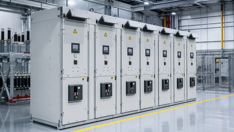
Passive protection relies on structural enclosure design to divert arc thermal energy and blast gases away from operating personnel. Standard switchgear enclosures provide mechanical ingress protection (IP ratings) but lack structural resilience against internal overpressure, whereas arc-resistant assemblies satisfy rigorous containment testing.
The table below contrasts standard low- and medium-voltage switchgear against arc-resistant assemblies engineered to IEC 62271-200 and IEEE C37.20.7 criteria:
| Design Feature | Standard Metal-Enclosed Switchgear | Arc-Resistant Switchgear (IEC 62271-200 IAC / IEEE C37.20.7) |
|---|---|---|
| Overpressure Containment | Standard 2 mm sheet steel; doors may burst open at >15 kPa internal blast. | Reinforced 3–4 mm structural steel with multi-point interlocking deadbolts. |
| Internal Arc Classification (IAC) | Non-rated; no formal arcing verification. | Rated AFLR (Accessibility: Front, Lateral, Rear) for up to 50 kA / 1.0 second. |
| Exhaust Gas Management | Uncontrolled release through standard ventilation louvres and panel seams. | Integrated pressure-relief top flaps and exhaust plenums directing gas outdoors. |
| Internal Partitioning | Basic Form 2 or Form 3 segregation. | Form 4b or LSC2B segregation with isolated busbar, cable, and breaker compartments. |
| Personnel Protection | Requires high-calibre arc-rated PPE during all maintenance procedures. | Guaranteed personnel safety with closed, latched compartment doors. |
| Capital Expenditure (CapEx) | Baseline capital expenditure. | 15% to 30% premium over conventional metal-clad lineups. |
In modern industrial applications, engineers often compare compact ring main units vs metal-clad switchgear, evaluating whether sealed, gas-insulated designs or fully ducted plenum systems deliver superior lifecycle arc protection.
Safe Operational Protocols: Electrical Arc Flash Safety and PPE Categories
Electrical arc flash safety mandates that operating procedures, physical approach boundaries, and personal protective equipment work concurrently to protect personnel from injury during maintenance or operational switching. NFPA 70E establishes three distinct approach boundaries surrounding energized electrical equipment:
- Arc Flash Boundary (AFB): The radial distance from an exposed energized conductor where incident energy dissipates to 1.2 cal/cm² (5.02 J/cm²). Anyone crossing within this perimeter must wear compliant, arc-rated protective clothing.
- Limited Approach Boundary: An electroshock protection distance designated for unqualified personnel, who must not cross unless escorted by a qualified electrical worker.
- Restricted Approach Boundary: The shock protection perimeter reserved strictly for qualified electricians wearing certified insulated gloves, tools, and arc-rated garments.
When operating switchgear where doors must be opened or covers removed, PPE must be selected according to verified incident energy calculations. NFPA 70E classifies PPE into four categories:
- PPE Category 1 (Minimum Arc Rating 4 cal/cm²): Arc-rated long-sleeve shirt and trousers (or arc-rated coverall), face shield with wrap-around brow guard, safety glasses, ear canal inserts, heavy-duty leather gloves, and leather safety footwear.
- PPE Category 2 (Minimum Arc Rating 8 cal/cm²): Arc-rated long-sleeve shirt and trousers or coverall (minimum 8 cal/cm²), arc-rated balaclava paired with an arc-rated face shield, safety glasses, hearing protection, leather work shoes, and insulated hand tools.
- PPE Category 3 (Minimum Arc Rating 25 cal/cm²): Arc flash suit jacket and trousers (or full coverall), integrated arc flash suit hood, arc-rated glove system, hearing protection, and safety footwear.
- PPE Category 4 (Minimum Arc Rating 40 cal/cm²): Multi-layer arc flash suit jacket and bib overalls providing complete 40 cal/cm² coverage, full-enclosure arc flash hood with supplied breathing or integrated cooling air, safety goggles, hearing protection, and leather outer gloves over insulating rubber gloves.
Modern plant standards increasingly mandate remote racking systems. Motorised racking trucks allow operators to insert or withdraw circuit breakers from 10 to 30 metres away, moving personnel entirely outside the Arc Flash Boundary during the highest-risk phase of switchgear operation.
Comprehensive Arc Flash Management Checklist for Substation RFQs
An effective arc flash management strategy starts at the procurement stage by drafting robust specifications into Request for Quotation (RFQ) documents. Failing to specify arc containment or optical trip integration during tender engineering results in costly retrofit installations later.
Procurement engineers can incorporate the following verification checklist directly into medium-voltage and low-voltage switchgear tenders:
- Enclosure rating: Must satisfy IEC 62271-200 Internal Arc Classification (IAC) AFLR for Medium Voltage (MV) or IEEE C37.20.7 Type 2B for Low Voltage (LV), verified by accredited third-party test laboratory certificates.
- Fault duration & magnitude: Withstand rating must meet or exceed the substation maximum available short-circuit level (e.g., 31.5 kA or 40 kA for 1.0 second duration).
- Pressure relief venting: Switchgear enclosures must include top-mounted, spring-loaded overpressure exhaust flaps venting into dedicated plenum ductwork routed outside the electrical room.
- Arc detection hardware: Lineups must include point-optical or bare-fibre sensors distributed in the cable termination compartment, circuit breaker cell, and main busbar chamber, integrated with high-speed digital relays.
- Safety interlocking: Mechanical door interlocks preventing compartment opening unless the primary circuit breaker is isolated and the integral earthing switch is closed.
- Maintenance switching modes: Low-voltage main circuit breakers must incorporate an external Energy Reducing Maintenance Switch (ERMS) that reduces instantaneous trip settings during plant walkthroughs and routine inspection.
- Remote operating facilities: Breaker racking mechanisms must feature umbilical motor-drive connections or wireless operational pendants.
Next steps: specifying and sourcing
Mitigating arc flash hazards requires pairing accurate system engineering calculations with factory-tested enclosure equipment. Whether upgrading an existing motor control centre or procuring integrated distribution infrastructure for a utility substation, specifying arc-resistant containment ensures long-term operational resilience and life safety.
Explore our engineering capabilities in custom HV & LV switchgear assemblies and prefabricated transformer substations designed to IEC and IEEE standards. When you are ready to evaluate equipment specifications, submit your single-line diagrams, target fault levels, and enclosure constraints directly to our engineering desk via the switchgear quotation portal to receive a detailed technical proposal.
Frequently asked questions
what is arc flash
An arc flash is a high-energy electrical explosion that occurs when electric current ionises the air between energized phase conductors or between a conductor and ground. It releases blinding light, severe blast pressure, and extreme heat exceeding 20,000 °C, vaporising metal conductors and severely burning unprotected personnel.
What is the difference between an arc flash and an arc blast?
An arc flash is the intense thermal and light energy radiation emitted by an arcing fault, while an arc blast is the explosive physical pressure wave caused by rapidly expanding vaporised copper and heated air. The flash burns tissue and ignites clothing, whereas the blast ruptures equipment enclosures and creates concussive physical trauma.
What causes an arc flash in electrical switchgear?
Arc flashes are typically triggered by human error during maintenance, such as accidental tool contact or improper breaker racking, as well as insulation breakdown, dust or moisture contamination, vermin ingress, or loose busbar bolt connections. Once insulation fails, an electrical discharge path forms across energized conductors.
How is the arc flash boundary calculated?
The arc flash boundary is calculated using IEEE 1584 mathematical formulas based on system voltage, available bolted fault current, conductor gap, and upstream protective device clearing time. It defines the physical perimeter within which incident energy dissipates down to 1.2 cal/cm², the threshold for second-degree burns.
Can standard switchgear protect workers from an arc flash?
Standard metal-enclosed switchgear is not certified to contain internal arcing faults; explosive overpressure can blast open standard doors and vent toxic plasma directly into the operating aisle. True protection requires arc-resistant switchgear certified to IEC 62271-200 (IAC AFLR) or IEEE C37.20.7 with structural reinforcement and exhaust plenums.
What is an Energy Reducing Maintenance Switch?
An Energy Reducing Maintenance Switch is an external control device that temporarily disables intentional selective coordination time delays on upstream circuit breakers during maintenance. This forces the breaker to trip instantly on minor overcurrents, significantly lowering clearing time and incident energy while technicians work within the arc flash boundary.
Tags: what is arc flash arc flash protection electrical arc flash arc flash safety arc flash protection system


