Key takeaways
- Metal enclosed switchgear houses switching and interrupting devices in an earthed metallic structure without requiring the continuous grounded sheet metal barriers demanded by metal-clad designs.
- Under IEEE C37.20.3, metal-enclosed interrupter switchgear utilises fixed or drawout power switches and fuses, whereas IEEE C37.20.2 metal-clad switchgear mandates drawout circuit breakers with fully isolated compartments.
- IEC 62271-200 classifies enclosed switchgear under Loss of Service Continuity (LSC) categories, where typical metal-enclosed assemblies without complete compartmentation achieve LSC1 or LSC2A ratings.
- Selecting metal-enclosed over metal-clad gear reduces footprint by 15% to 30% and capital cost by up to 40% when high-cycling drawout breakers are not required for radial feeders.
- Factory acceptance testing (FAT) for metal-enclosed switchgear requires power-frequency withstand, insulation resistance, mechanical endurance verification, and primary injection testing across bus joints.
Quick answer: Metal enclosed switchgear is an electrical distribution assembly enclosed on all sides by earthed sheet metal containing primary switching devices, buses, and connections, designed to control and protect medium-voltage feeders. Unlike metal-clad gear, it does not require full metallic compartmentalisation between internal components, making it a cost-effective, compact solution for medium-voltage primary distribution.
Industrial plants, institutional campuses, and commercial infrastructure demand dependable incoming power distribution and circuit protection without incurring unnecessary capital expenses. In radial distribution networks, renewable generation tie-ins, and secondary substations, specifying fully segregated switchgear can introduce surplus footprint, weight, and procurement costs. Understanding the physical layout, electrical ratings, and operational limitations of metal enclosed switchgear enables consulting engineers and project developers to match system protection requirements precisely to substation architecture.
What Is Metal Enclosed Switchgear?
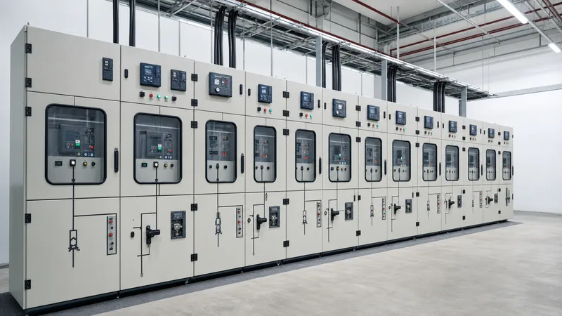
Metal enclosed switchgear is a factory-assembled power distribution structure completely enclosed on all sides by grounded metal sheets, housing switching and protective devices such as vacuum switches, fuses, circuit breakers, and instrument transformers. As defined in IEEE C37.20.3 Clause 4, metal-enclosed interrupter switchgear consists of an assembly containing interrupter switches, power fuses, busing, and connections housed in an earthed steel framework. The international standard IEC 62271-200 Clause 3.107 defines alternating current metal-enclosed switchgear and controlgear as assemblies where all internal components are enclosed inside an external grounded metallic housing designed to protect operators against accidental contact with live parts.
The primary function of this enclosed switchgear is to provide safe sectionalising, isolation, short-circuit protection, and switching control for medium-voltage networks operating typically between 2.4 kV and 38 kV. While an assembly qualifies as metal enclosed because its outer shell is metallic and grounded, its internal volume may contain common spaces where busbars, disconnect switches, and incoming cable terminators share the same air space or use non-metallic barriers. For broader architectural context on medium-voltage gear ratings, refer to our MV switchgear engineering guide.
Metal Clad vs Metal Enclosed: Key Engineering Differences
The technical distinction in metal clad vs metal enclosed switchgear centres on internal segregation, component withdrawability, and shutter isolation. In standard North American (IEEE) and international (IEC) practice, all metal-clad switchgear is structurally metal-enclosed, but not all metal enclosed assemblies qualify as metal-clad. The comparison between metal enclosed vs metal clad switchgear determines both capital expenditure and system maintainability.
Under IEEE C37.20.2, metalclad switchgear mandates four distinct physical features: 100% grounded metal barriers isolating the circuit breaker, bus compartment, cable compartment, and low-voltage control section; fully drawout circuit breakers; automatic grounded metal shutters that close when the breaker is racked out; and insulated main busbars. By comparison, IEEE C37.20.3 metal-enclosed switchgear permits fixed-mounted load-break switches or circuit breakers, common internal air spaces without grounded metal partitions, bare or insulated busbars, and optional mechanical shutters. To review the specialised construction of segregated assemblies, read our metal clad switchgear engineering guide.
| Engineering Parameter | Metal Enclosed Switchgear (IEEE C37.20.3 / IEC LSC1 or LSC2A) | Metal Clad Switchgear (IEEE C37.20.2 / IEC LSC2B) |
|---|---|---|
| Internal Compartmentalisation | Common internal volume or non-metallic barriers between sections | Fully isolated compartments divided by grounded metal sheets |
| Switching Mechanism | Fixed or drawout switch/fuse or circuit breaker | Strictly drawout vacuum or SF6 circuit breaker |
| Automatic Protective Shutters | Optional; often manual or omitted on fixed switches | Mandatory automatic earthed metal shutters |
| Busbar Insulation | Bare copper/aluminium or sleeved (optional depending on spec) | Mandatory continuous insulation on all phase buses |
| Loss of Service Continuity (IEC) | Typically LSC1 or LSC2A (cables earthed during bus access) | LSC2B (compartments serviceable while bus remains live) |
| Average Footprint | Base reference (100%) | 115% to 140% larger floor area required |
| Relative Capital Cost | Base reference (100%) | 140% to 175% higher cost per vertical section |
Internal Architecture and Partitioning Classes
Internal architecture dictates the level of operator safety and service continuity achievable during maintenance on an energized lineup. In international installations governed by IEC 62271-200, assemblies are categorised by partition class and Loss of Service Continuity (LSC). Partition classes define the material of internal barriers between compartments: Class PM utilizes metallic partitions that are bonded to the primary earth bar, whereas Class PI utilizes non-metallic insulating barriers.
The LSC rating determines which functional units can remain energised when accessing a specific compartment:
- LSC1: Accessing any compartment requires shutting down the entire lineup; typical of compact fused-switch bays where the bus passes directly through the termination area.
- LSC2A: Opening the cable compartment requires de-energising that specific functional unit, but the main horizontal busbar compartment remains energized. Metal enclosed switchgear configured with interrupter switches commonly complies with LSC2A.
- LSC2B: Provides independent access to the switching compartment, the cable compartment, and the busbar compartment without disconnecting any adjacent circuits. This configuration is standard for fully partitioned installations.
For installations where personal safety and containment of internal thermal hazards are paramount, specifying internal arc classification (IAC) under IEC 62271-200 Annex A provides verified operator protection against high-energy explosive faults. You can review safety boundaries and mitigation schemes in our analysis of arc flash safety and containment.
Electrical Ratings and Bus Sizing Criteria
Sizing medium-voltage enclosed switchgear requires matching rated voltage, continuous operational current, short-time withstand current, and basic impulse level (BIL) to site conditions. In accordance with IEEE C37.20.3 Table 1 and IEC 62271-1 Table 1, nominal system voltages correlate to maximum design voltages that account for transient utility swells.
The continuous current carrying capacity of the copper busbar depends on the permissible temperature rise defined in IEEE C37.20.3 Clause 5.4.2, which limits total bus temperature to 105°C (a 65°C rise over a 40°C ambient) when using silver-plated or tin-plated bolted joints. When sizing copper conductors for a 1200 A rating, an engineer applies a standard current density guideline of 1.2 to 1.5 A/mm² for natural convection inside non-ventilated enclosures:
For a continuous current of 1200 A at 1.2 A/mm², the required cross-sectional copper area is:
A = I / J = 1200 A / 1.2 A/mm² = 1000 mm²
This is achieved using two bars of 50 mm × 10 mm copper per phase, separated by a 10 mm air gap to ensure natural air cooling. The assembly must also withstand the electromechanical forces generated during short-circuit conditions. The peak withstand current (Ipeak) is calculated from the rated short-time symmetrical withstand current (Ik) using the peak factor k per IEC 62271-1:
Ipeak = 2.5 × Ik (at 50 Hz, X/R = 14) or 2.6 × Ik (at 60 Hz)
For a 25 kA symmetrical root-mean-square (RMS) rating at 60 Hz, the bracing insulators must withstand a mechanical peak force corresponding to 65 kA peak. For complete substation integration calculations, see our electrical switchgear design guide.
Specification and Factory Inspection Checklist
A structured technical specification prevents misinterpretation during competitive bidding and ensures that the factory executes all critical safety interlocks correctly. When preparing an inquiry for metal enclosed switchgear, include environmental parameters, mechanical interlocking logic, and required routine factory tests per IEEE C37.20.3 Clause 7.
Follow this five-step engineering inspection sequence during Factory Acceptance Testing (FAT):
- Dimensional and Enclosure Verification: Measure external sheet steel thickness (minimum 2.0 mm / 14-gauge for structural panels per IEEE C37.20.3), degree of ingress protection (IP3X to IP54 per IEC 60529 or NEMA 1/3R), and paint thickness (minimum 50 to 80 microns dry film).
- Mechanical Interlocking Validation: Verify that the door cannot be opened while the load-break switch is closed, and that the earth switch cannot close when the primary disconnect is in the closed position. Test key-interlock sequences with upstream transformers.
- Insulation Resistance and Power-Frequency Withstand: Measure phase-to-phase and phase-to-earth insulation using a 2500 V or 5000 V megohmmeter (minimum reading 1000 MΩ), followed by a one-minute power-frequency dielectric withstand test at the rated test voltage (e.g., 38 kV dry withstand for 15 kV nominal gear per IEEE C37.20.3 Table 1).
- Primary Contact Resistance Measurement: Conduct a micro-ohmmeter test using 100 A DC injection across all main joints, bolted busbars, and switch blades. Bolted joints must demonstrate low resistance, typically under 35 micro-ohms per connection.
- Secondary Control and Wiring Check: Verify all auxiliary relays, heater circuits, current transformer polarity and secondary burdens, potential transformer ratios, and terminal strip labeling against the approved schematic diagrams.
Next steps: specifying and sourcing
Selecting the optimal medium-voltage switchgear architecture demands balancing upfront capital expenditure against lifetime maintenance, operator safety, and operational flexibility. If your facility requires incoming service entrance gear, primary transformer disconnects, or secondary distribution lineups, specifying fit-for-purpose equipment avoids excessive project overheads. Explore our engineered HV and LV switchgear assemblies and integrated prefabricated transformer substations designed to IEC and IEEE standards. To evaluate your site single-line diagrams or receive an itemised equipment quotation, submit your project schedules directly through our switchgear quotation portal.
Frequently asked questions
What is the difference between metal clad vs metal enclosed switchgear?
Metal-clad switchgear requires fully compartmentalised grounded metal barriers between all sections, drawout circuit breakers, and automatic shutters. Metal enclosed switchgear houses equipment in a grounded metallic shell but permits common internal volumes, non-metallic barriers, and fixed-mounted load-break switches.
What standards govern metal enclosed switchgear?
In North America, IEEE C37.20.3 governs metal-enclosed interrupter switchgear, while IEEE C37.20.1 covers low-voltage power circuit breaker switchgear. Internationally, IEC 62271-200 governs AC metal-enclosed switchgear and controlgear up to 52 kV.
Can metal enclosed switchgear be installed outdoors?
Yes, metal enclosed switchgear can be fabricated for outdoor environments by applying weatherproof NEMA 3R or NEMA 4 enclosures, or IEC ingress protection ratings from IP44 up to IP55, including space heaters to prevent internal condensation.
Are switches in metal enclosed switchgear fixed or drawout?
Most metal enclosed assemblies employ fixed-mounted interrupter switches or circuit breakers to minimize equipment depth and cost. However, drawout mechanisms are available as an engineered option for installations requiring fast isolation and replacement.
What is the typical short-circuit rating for metal enclosed switchgear?
Standard medium-voltage metal enclosed switchgear is rated for short-circuit withstand levels between 16 kA and 40 kA symmetrical RMS for 1 to 3 seconds, with peak withstand ratings reaching 40 kA to 104 kA.
Does metal enclosed switchgear provide arc flash containment?
Standard metal enclosed switchgear does not contain internal arc blasts unless specifically designed and type-tested to IEEE C37.20.7 or IEC 62271-200 Annex A as arc-resistant switchgear with internal pressure-relief flaps and exhaust ducts.
Tags: metal enclosed switchgear metal enclosed metal clad vs metal enclosed enclosed switchgear metalclad switchgear


