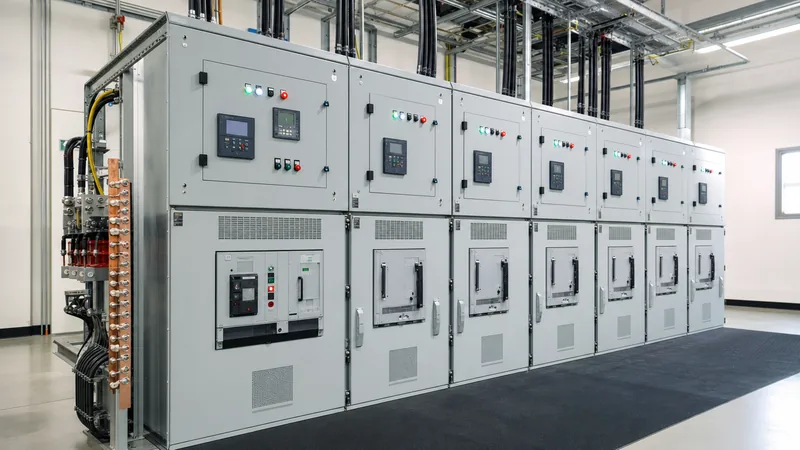
Key takeaways
- Electrical switchgear provides vital circuit interruption, operational isolation, and system protection across low-, medium-, and high-voltage power networks.
- Busbar ratings must be validated for continuous thermal capacity as well as dynamic peak withstand current (Ip) and short-time withstand current (Ith) per IEC 62271-1 clause 6.5.
- Internal arc classification (IAC AFLR) per IEC 62271-200 ensures assembly containment against blast pressures during catastrophic short-circuit conditions.
- Transformer switchgear selection requires matching incoming fault levels, rated breaking capacity, and coordinated relay protection curves with the transformer damage curve.
- Factory Acceptance Testing (FAT) must systematically verify dielectric insulation levels (power-frequency and lightning impulse), breaker timing, and contact resistance before shipment.
Quick answer: Electrical switchgear is an integrated assembly of electrical disconnect switches, fuses, circuit breakers, busbars, and protective relays designed to isolate, control, and protect electrical equipment. It enables normal load switching, isolates faulty downstream sections without disrupting upstream operations, and protects industrial infrastructure from short circuits, overloads, and earth faults.
In industrial facilities, utility distribution networks, and renewable generation plants, the reliability of downstream loads depends entirely on the correct design and operation of switchgear assemblies. Modern power distribution relies on coordinated apparatus that can interrupt immense fault energies within milliseconds while maintaining total physical safety for operating personnel. Understanding how this equipment is designed, categorised, and verified against international standards is critical for plant engineers, electrical contractors, and specification teams.
What Is Electrical Switchgear and How Does It Work?
To define electrical switchgear, it is best understood as the centralised collection of switching, measuring, and protective devices housed in a grounded metal structure to manage electrical power distribution. The term switch gear means the complete mechanical and electrical switching apparatus that regulates energy flow between sources, such as incoming utility feeders or generators, and downstream loads including transformers, motor control centres, and distribution boards.
How does switchgear work during normal and abnormal operating states? Under steady-state operations, switchgear permits routine energisation and de-energisation of circuits via manually or electrically operated mechanisms. When abnormal conditions such as short circuits, phase-to-earth faults, or phase unbalances occur, instrument transformers measure the anomalous current or voltage magnitudes. These secondary signals are continuously fed into numerical protective relays. Once a fault threshold defined by the engineer's protection coordination curve is exceeded, the relay energises the trip coil of the associated circuit breaker.
The circuit breaker mechanism then releases stored mechanical energy—typically from a charged spring or hydraulic-pneumatic system—to separate the primary contacts inside an insulating interruption medium such as a vacuum bottle or sulphur hexafluoride (SF6) chamber. The arc generated during contact separation is rapidly cooled and extinguished at current zero, isolating the faulty feeder within 30 to 60 milliseconds. This rapid clearance protects upstream transformers and parallel circuits from thermal degradation and severe mechanical forces.
Essential Features of Switchgear Assemblies
The essential features of switchgear are engineered to guarantee operator safety, maintain operational continuity, and withstand transient electrodynamic stresses. Standard IEC 62271-200 defines the primary design characteristics that modern medium-voltage metal-enclosed assemblies must incorporate to ensure safe operation throughout their service lifecycle.
Every professional switch gear panel incorporates the following core engineering features:
- Compartmentalised Segregation: Distinct metal partitions isolate the busbar compartment, circuit breaker compartment, cable connection compartment, and low-voltage control instrument compartment, preventing an electrical fault in one zone from propagating to adjacent sections.
- Fail-Safe Mechanical Interlocks: Interlocking mechanisms prevent dangerous operations, ensuring that the circuit breaker cannot be racked in or out while closed, access doors cannot be opened unless the circuit is earthed, and the earthing switch cannot close onto an energised feeder.
- Internal Arc Classification (IAC): Certified assemblies undergo destructive testing per IEC 62271-200 clause 6.106 to verify that escaping plasma gases and pressure waves are safely vented upward away from personnel positioned at the front (A), lateral (L), and rear (R) accessible faces.
- Service Continuity Loss (LSC) Categorisation: Switchboards classified as LSC2B allow the cable and breaker compartments of a single panel to be safely accessed for maintenance while adjacent panels and main busbars remain fully energised.
- Continuous Earth Bus System: A high-conductivity copper earthing bar spans the entire length of the switchboard, providing a low-impedance path to earth capable of carrying full rated short-circuit current without dangerous potential rise.
Primary Electrical Switchgear Components
Electrical switchgear components work as an integrated electro-mechanical system to sense conditions, direct primary energy, and interrupt high-energy faults. Each component must be matched to both continuous operational duty and transient disturbance ratings.
The primary components engineered inside each switch gear panel include:
- Circuit Breakers: The active switching element, using vacuum interrupters for medium-voltage duties (up to 40.5 kV) or air-break mechanisms for low-voltage systems (up to 1,000 V), rated to make and break continuous load currents and rated short-circuit fault currents.
- Primary Busbars: High-conductivity electrolytic copper or aluminium conductors, supported by cycloaliphatic epoxy or porcelain insulators, sized to handle thermal expansion and electrodynamic forces during through-fault conditions.
- Current Transformers (CTs) and Voltage Transformers (VTs): Precision instrument transformers that step down primary line currents and phase voltages to standardised secondary values (such as 1 A, 5 A, 110 V) for metering and relay protection.
- Protective Relays: Microprocessor-based numerical relays executing overcurrent (ANSI 51), instantaneous short-circuit (ANSI 50), directional earth fault (ANSI 67N), and differential protection (ANSI 87) algorithms. For deep integration details, consult our engineering guide on transformer protection systems.
- Earthing Switches: Fast-acting mechanical switches with snap-action spring mechanisms engineered to close safely against accidental live busbar potentials (making capacity) per IEC 62271-102.
- Cable Terminations and Surge Arresters: Cold-shrink or heat-shrink termination systems combined with metal-oxide gapless surge arresters (Class 1 or 2 discharge) to clamp lightning and switching transient overvoltages.
Types of Electrical Switchgear by Voltage Classification
Types of electrical switchgear are fundamentally categorised by operating voltage level, insulation medium, and mechanical construction. Standards including IEC 62271 (medium and high voltage) and IEC 61439 (low voltage) delineate distinct construction and safety parameters across these categories.
The three main voltage classifications encompass:
- Low-Voltage (LV) Switchgear: Operating up to 1,000 V AC, LV switchboards (often configured as power distribution centres or motor control centres) rely on air circuit breakers (ACBs) and moulded case circuit breakers (MCCBs) per IEC 61439-2.
- Medium-Voltage (MV) Switchgear: Spanning 1 kV up to 52 kV, medium voltage switchgear is the backbone of utility distribution, renewable collector systems, and heavy industrial distribution. MV gear is commonly specified as either metal-clad switchgear with draw-out vacuum circuit breakers or sealed gas-insulated ring main units. Detailed selection criteria can be explored in our comparison between ring main units and metal-clad switchgear.
- High-Voltage (HV) Switchgear: Operating above 52 kV up to 550 kV and beyond, HV switchgear is deployed in transmission substations and bulk power transfers, utilising dead-tank breakers, live-tank gas-insulated switchgear (GIS), or hybrid switchgear modules.
The following engineering comparison details the mechanical and electrical parameters across low and medium voltage switchgear types:
| Parameter / Feature | Low-Voltage Switchgear (LV) | Medium-Voltage Metal-Clad (AIS) | Medium-Voltage Gas-Insulated (GIS) |
|---|---|---|---|
| Applicable Standards | IEC 61439-2 / UL 891 | IEC 62271-200 / IEEE C37.20.2 | IEC 62271-200 / IEEE C37.20.7 |
| Nominal Voltage Range | Up to 1,000 V AC | 3.3 kV to 40.5 kV | 7.2 kV to 40.5 kV |
| Insulation Medium | Air (atmospheric) | Air (solid insulated bus) | SF6 or dry air gas mixture |
| Interruption Technology | Air break (de-ion chutes) | Vacuum interrupter | Vacuum bottle in sealed tank |
| Rated Continuous Current | 630 A to 6,300 A | 630 A to 4,000 A | 630 A to 2,500 A |
| Rated Breaking Capacity | 25 kA to 100 kA rms | 16 kA to 50 kA rms | 20 kA to 40 kA rms |
| Footprint Requirement | Standard modular width | 100% baseline footprint | 40% to 60% of AIS footprint |
| Maintenance Demands | Periodic contact cleaning | Annual mechanism grease/check | Virtually maintenance-free tank |
Substation Switchgear and Transformer Switchgear Integration
Substation switchgear and transformer switchgear form the primary interface between power transmission lines, intermediate distribution grids, and client step-down transformers. When integrating switchgear with power transformers, the protection scheme must account for inrush currents, through-fault withstand capabilities, and impedance constraints.
A transformer switchgear lineup typically houses the dedicated primary feeder breaker, primary CTs/VTs, and an earthing switch adjacent to the transformer terminals. During transformer energisation, transient core magnetisation causes magnetising inrush currents up to 8 to 12 times the rated full-load current for several cycles. The protection relays inside the transformer switchgear must employ second-harmonic restraint (typically set to block tripping if harmonic content exceeds 15% to 20%) to prevent nuisance tripping during line energisation.
Coordination between the switchgear and the transformer requires synchronising the breaker clearing time with the transformer thermal and mechanical damage limits governed by IEEE C57.109 or IEC 60076-5. For detailed calculations on matching transformer parameters to substation designs, review our guide on substation transformer engineering and siting as well as our interactive transformer sizing calculator guide.
Engineering Sizing and Busbar Short-Circuit Calculations
Switchgear busbars must be sized to carry continuous rated current without exceeding standard temperature rise limits (typically 65 K rise above 40°C ambient for silver-plated joints per IEC 62271-1 Table 14) and withstand electrodynamic shock during faults. Calculating the required busbar cross-section and dynamic withstand confirms that the switchboard will not undergo mechanical collapse or thermal fusion during an external network fault.
To calculate the thermal short-time withstand cross-sectional area ($A$) of a copper busbar for a rated duration ($t$), use the standard thermal equilibrium equation from IEC 60865-1:
$$A = \frac{I_{th}}{\beta} \sqrt{\frac{t}{\Delta\theta}}$$
Where $I_{th}$ is the root-mean-square short-circuit current, $\beta$ is the material constant (for copper, $\beta \approx 13$ in SI units), and $\Delta\theta$ is the allowable transient temperature rise during the fault (typically 120 K, rising from 105°C operating limit to 225°C emergency limit).
Worked Engineering Example:
- System Prospective Short-Circuit: $I_{sc} = 25\text{ kA rms}$
- Fault Duration: $t = 3.0\text{ seconds}$
- Peak Factor ($k$ per IEC 60909): $2.55$, giving a peak withstand current $I_p = 25 \times 2.55 = 63.75\text{ kA peak}$
- Allowable Temperature Rise: $\Delta\theta = 120\text{ K}$
Calculating the minimum theoretical thermal copper area:
$$A = \frac{25000}{13} \times \sqrt{\frac{3.0}{120}} = 1923.08 \times 0.1581 = 304.04\text{ mm}^2$$
While $304\text{ mm}^2$ satisfies thermal withstand over three seconds, the continuous current requirement dictates actual busbar dimensions. If the switchgear carries $1,600\text{ A}$ nominal continuous current at $40^\circ\text{C}$ ambient, standard practice requires two copper bars of $80\text{ mm} \times 10\text{ mm}$ per phase (cross-sectional area of $1,600\text{ mm}^2$), providing a thermal safety margin that easily exceeds the minimum fault threshold.
Next, the mechanical electrodynamic force ($F_m$) exerted between horizontal busbar phases spaced $a = 200\text{ mm}$ apart with support span $l = 800\text{ mm}$ under peak current $I_p = 63.75\text{ kA}$ is calculated per IEC 60865-1:
$$F_m = \frac{\mu_0}{2\pi} \times \frac{I_p^2 \times l}{a} = \left(2 \times 10^{-7}\right) \times \frac{\left(63750\right)^2 \times 0.80}{0.20} = 3,251.25\text{ N}$$
The epoxy post insulators selected to support these busbars must have a rated mechanical cantilever bending strength greater than $3.25\text{ kN}$ plus an engineering safety factor of at least $1.5$, meaning insulators rated for $\ge 5.0\text{ kN}$ must be specified in the bill of materials.
Indoor vs Outdoor Switchgear and Environmental Enclosures
Indoor and outdoor switchgear designs differ primarily in their enclosure engineering, corrosion protection, and internal thermal dissipation mechanisms. Outdoor switchgear installations must withstand driving rain, solar radiation, humidity cycling, and wind-borne particulate ingress without insulation degradation.
For indoor switchgear installations, enclosures are typically rated IP3X to IP42 per IEC 60529 or NEMA 1 to NEMA 12 per NEMA 250. These structures rely on the climate-controlled or ventilated switchroom to mitigate condensation and extreme thermal loading.
In contrast, outdoor switchgear is engineered within weatherproof walk-in or non-walk-in kiosks, prefabricated containerised substations, or pad-mounted enclosures meeting IP54 or IP55 (NEMA 3R or NEMA 4X) requirements. Outdoor assemblies incorporate:
- Internal thermostatically controlled anti-condensation heaters to keep the internal air temperature above the dew point.
- Dual-roof canopies with pitched slopes and solar radiation shielding to minimise thermal heat absorption during peak ambient exposure.
- Electrostatic powder-coated galvanised sheet steel (minimum 2.0 mm thickness) or marine-grade aluminium passing ASTM B117 salt spray testing for 1,000+ hours.
- Gland plates with neoprene or EPDM gaskets to prevent moisture migration through power cable trenches.
Factory Acceptance Testing (FAT) and Sourcing Checklist
Factory Acceptance Testing (FAT) validates the mechanical operability, electrical clearances, and dielectric integrity of electrical switchgear before dispatch to the project site. Sourcing engineers must avoid the operational and legal risks associated with undocumented used switchgear, which frequently exhibits degraded insulation, obsolete trip units, and voided type test certifications.
When reviewing switchgear testing at the manufacturing facility, engineers should execute the following inspection sequence:
- Dimensional and Visual Inspection: Verify overall panel dimensions, busbar plating thickness, paint thickness (minimum 80 micrometres dry film thickness), creepage distances, and phase clearances per approved general arrangement drawings.
- Mechanical Operation and Interlock Checks: Perform 20 manual and electrical open/close cycles on circuit breakers, verify draw-out racking mechanisms, and validate safety shutter closures and interlock blockings.
- Dielectric Power-Frequency Withstand Test: Subject primary circuits to power-frequency withstand voltage (e.g., 28 kV rms for 12 kV switchgear, 95 kV rms for 36 kV switchgear) for 60 seconds per IEC 62271-200 clause 7.1.
- Auxiliary Circuit Insulation Test: Apply 2.0 kV AC for one minute to all secondary wiring, terminal blocks, trip coils, and instrument control circuits.
- Main Circuit Contact Resistance Measurement: Measure micro-ohm resistance across all primary joints and breaker poles using a 100 A DC digital micro-ohmmeter; values should not deviate by more than 20% from type-test reference levels.
- Circuit Breaker Timing Analysis: Record closing times, opening times, and contact bounce via digital timing analysers to verify adherence to manufacturer tolerances (typically under 45 ms opening time).
- Secondary Protection Relay Injection: Perform secondary current and voltage injection to confirm trip logic, pickup current thresholds, and trip curve timing against the engineer's protection coordination schedule.
Next steps: specifying and sourcing
Specifying the correct switchgear requires a complete single-line diagram (SLD), prospective short-circuit fault levels, system nominal voltage, operating frequency, and target enclosure protection classes. To begin your project procurement or technical evaluation, explore our certified HV and LV switchgear assemblies and prefabricated compact transformer substations engineered to IEC and IEEE standards. Submit your single-line schematics and engineering specifications directly to our design team via our switchgear quotation page or reach out through our engineering contact portal for custom bids and design reviews.
Frequently asked questions
what is switch gear
Switchgear is an integrated assembly of switching, interrupting, and protection devices such as circuit breakers, disconnectors, and busbars. Its primary function is to control power distribution and protect upstream and downstream electrical equipment by isolating electrical faults rapidly and safely.
what does a switchgear do
A switchgear controls the flow of electrical power, permits manual or remote switching of circuits, and automatically isolates faulted circuits. It prevents electrical fires and equipment destruction by interrupting dangerous short circuits, overloads, and ground faults within milliseconds.
what are switchgears
Switchgears are metal-enclosed electrical assemblies containing power switching and protection apparatus used in utility, industrial, and commercial substations. They connect incoming power supplies to distribution networks, enabling safe routine maintenance and instant automatic fault clearance.
how does switchgear work
Switchgear operates by sensing electrical faults through instrument transformers and numerical relays that trigger a circuit breaker mechanism. The circuit breaker rapidly separates its internal electrical contacts inside vacuum, air, or gas chambers to extinguish the resulting arc and de-energise the compromised circuit.
what is the difference between switchgear and a switchboard
Switchgear features individually segregated, metal-clad compartments with draw-out circuit breakers designed for higher fault levels and high service continuity per standards like IEEE C37.20.2. Switchboards are typically front-accessible, compartmentalised assemblies with fixed or plug-in breakers suited for lower fault duties.
why is internal arc classification important for switchgear
Internal arc classification (IAC) verifies that a switchgear enclosure can safely contain and vent violent thermal blast pressures and ionised gases caused by an internal short circuit. It protects operating personnel standing nearby from burns, fragmentation, and toxic fumes during an catastrophic internal fault.
Tags: electrical switchgear medium voltage switchgear substation switchgear transformer switchgear switch gear panel


