Key takeaways
- Bus duct and busway mean the same product; NEC Article 368 calls it busway, while IEC 61439-6 calls it a busbar trunking system.
- Low-voltage sandwich busway is commonly built from about 400 A to 6,300 A, with short-time withstand ratings often between 50 kA and 150 kA for 1 s.
- Voltage drop is calculated as ΔV = √3 × I × L × (R cosφ + X sinφ), using the busway's per-meter resistance and reactance at operating temperature.
- A 1,600 kVA transformer at 400 V draws about 2,309 A full load, so a 2,500 A busway is the usual flanged connection to its LV switchboard.
- Busway systems in the US are listed to UL 857 and installed per NEC Article 368; fire-rated wall and floor penetrations need tested firestop assemblies.
Quick answer: A bus duct (busway) is a factory-built enclosure containing insulated copper or aluminum bars that carries large currents, typically 400–6,300 A at low voltage, between transformers, switchboards and loads. Feeder busway moves bulk power point to point; plug-in busway adds tap-off bus plugs along its length. It replaces multiple parallel cable runs with a compact, low-impedance, modular conductor.
Wherever current climbs past roughly 1,000 A, cable becomes awkward: six or eight parallel sets per phase, large bending radii, heavy trays and many terminations that each add a failure point. A bus duct solves that with rigid busbars in a compact steel or aluminum housing that can be routed vertically through a riser, horizontally across a plant, or straight from a transformer throat into a switchboard.
This guide is for electrical engineers, contractors and facility owners who need to specify or review a busway electrical system. It covers construction types, busway components, current and short-circuit ratings, a worked voltage drop calculation, how bus duct compares with cable, and what to put in an RFQ so the busway, transformer and switchgear interfaces match.
What Is a Busway and How Does an Electrical Bus Duct Work?
A busway is a prefabricated, enclosed assembly of busbars, insulation and housing that distributes electrical power in modular lengths joined by bolted connectors. Each phase bar, plus a neutral and often an integral or separate ground bar, runs the full length of a section. Sections typically come in lengths of 1–3 m (or 10 ft in North American practice) and are joined with a joint pack, a bolted splice that clamps adjacent bars together under a calibrated torque.
Current flows through the bars exactly as it would through cable, but the geometry is very different. In a sandwich design the phase bars are stacked tightly with only thin insulation between them, so the magnetic fields of opposite phases largely cancel. That gives a low reactance per meter, which reduces voltage drop and improves current sharing compared with many paralleled cables.
Busway vs bus duct: is there a difference?
No functional difference. "Bus duct" is the older term, still common in Asia, the Middle East and in medium-voltage work. "Busway" is the term used by the NEC (Article 368) and UL 857 in North America. IEC 61439-6 uses "busbar trunking system" (BTS). Searches for "bus busway" or "bus way electrical" mean the same product. In medium voltage, the equivalent products are non-segregated, segregated and isolated-phase bus duct, rated under IEEE C37.23.
Bus Duct System Types: Feeder, Plug-In, Trolley and MV
A busway system is chosen first by function, then by construction. The table below summarizes the main families.
| Type | Function | Typical range | Typical use |
|---|---|---|---|
| Feeder busway | Point-to-point bulk power, no tap-offs | 800–6,300 A, LV | Transformer to main switchboard, switchboard to switchboard |
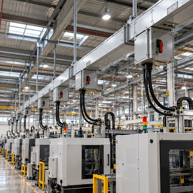
| Plug-in busway | Tap-off openings every 0.5–1 m for bus plugs | 225–5,000 A, LV | Factory floors, high-rise risers, data center rows |
| Lighting / trolley busway | Small continuous track for light loads or moving pickups | 25–250 A | Lighting runs, cranes, test benches |
| Cast-resin bus | Bars fully encapsulated in resin | Up to about 6,300 A, IP68 | Wet, corrosive or outdoor routes |
| Non-segregated phase bus (MV) | Bars in common enclosure, no barriers | 4.16–38 kV, 1,200–6,000 A | Generator and transformer to MV switchgear |
| Isolated-phase bus (MV) | Each phase in its own grounded tube | Generator voltage, 10,000 A+ | Power plant generator leads |
Sandwich vs ventilated construction
Sandwich (non-ventilated) busway has bars in direct contact through insulation, giving low impedance, high short-circuit strength and good fire performance, because there is no chimney effect in vertical risers. Ventilated (air-insulated) busway spaces the bars in free air; it runs cooler per unit of copper but has higher reactance and usually needs larger sizes for the same rating. Most new LV projects use sandwich designs in aluminum or copper.
Busway Components and Bus Plugs Explained
A typical busway electrical system is assembled from a catalog of standard busway components, all type-tested together. Knowing the parts helps you read layout drawings and bills of quantities.
- Straight lengths: the main run, feeder or plug-in style.
- Joint packs: bolted splices between sections; many use a single-bolt design with a break-off or indicator head to confirm torque.
- Elbows, offsets and tees: fittings that follow the building and branch the run.
- Flanged ends: connect directly to a transformer throat or switchboard; dimensions must be coordinated with the equipment supplier.
- Expansion fittings: absorb thermal growth on long straight runs and across building expansion joints.
- Hangers, spring hangers and wall/floor flanges: support the run and seal fire-rated penetrations.
What are bus plugs?
A bus plug is a tap-off unit that hooks onto a plug-in busway opening and feeds a branch circuit through a built-in fuse switch or molded-case circuit breaker. Bus plugs electrical units range from about 16 A to 800 A or more. They are interlocked so the cover cannot be opened with the device on, and most designs make the ground stab first and break it last. Plug-in busway lets a factory or data center add or move loads without new cable runs, which is its main commercial advantage. Installing or removing bus plugs on an energized run should only be done where the manufacturer's instructions and the site's electrical safety program, including an arc flash risk assessment, permit it.
How Are Busway Ratings Specified?
Every electrical bus duct is defined by a handful of ratings. Get these right on the data sheet and most coordination problems disappear.
| Rating | What it means | Typical values / standard |
|---|---|---|
| Rated current (In or ampacity) | Continuous current at stated ambient without exceeding temperature rise | 400–6,300 A; IEC 61439-6, UL 857 |
| Rated operational voltage | System voltage the busway is designed for | Up to 1,000 V AC (IEC); 600 V (UL) |
| Short-time withstand (Icw) | RMS current carried for 1 s without damage | 25–150 kA, rising with frame size |
| Peak withstand (Ipk) | First-peak mechanical force capability | Typically 2.0–2.2 × Icw |
| Degree of protection | Ingress protection of the enclosure | IP40 indoor to IP55/IP66 or IP68 cast-resin |
| Fire resistance | Integrity of wall/floor barrier | Tested firestop, often 2 h |
| Resistance and reactance | Per-meter impedance for voltage drop and fault studies | Given by manufacturer, mΩ/m |
The short-time rating must be at least the prospective fault current at the busway's location, which you obtain from a fault current calculation at the transformer secondary. Ambient matters too: catalog ampacity is usually stated at 35 °C or 40 °C average ambient, so a run through a hot plant room may need derating. For enclosure protection codes and their North American equivalents, see the comparison of NEMA vs IP ratings.
Worked Example: Sizing a Feeder Busway and Checking Voltage Drop
Consider a 1,600 kVA, 11 kV/400 V dry-type transformer feeding a main LV switchboard 60 m away. The design load is 2,000 A at 0.85 power factor.
Step 1, transformer full-load current: I = S / (√3 × V) = 1,600,000 / (1.732 × 400) = 2,309 A. The busway must carry full transformer output, so select the next standard rating, 2,500 A. The method behind this is covered in our transformer current calculation formulas guide.
Step 2, voltage drop: the formula for a three-phase busway is ΔV = √3 × I × L × (R cosφ + X sinφ), where R and X are per-phase values per meter at operating temperature. Assume the manufacturer gives R = 0.022 mΩ/m and X = 0.011 mΩ/m for the 2,500 A copper frame.
- R × L = 0.022 × 60 = 1.32 mΩ; X × L = 0.011 × 60 = 0.66 mΩ
- cosφ = 0.85, sinφ = 0.527
- R cosφ + X sinφ = 1.122 + 0.348 = 1.470 mΩ
ΔV = 1.732 × 2,000 × 0.00147 = 5.1 V
That is 5.1 / 400 = 1.3% drop, comfortably below a typical 2% feeder allowance. For plug-in busway with distributed loads, the drop is roughly half of the value calculated with all load at the far end, because the average current along the run is lower.
Step 3, short-circuit check: with 6% impedance and an infinite source, prospective fault current at the secondary is about 2,309 / 0.06 = 38.5 kA, so a frame with Icw of 50 kA (1 s) gives margin. A cable alternative would need roughly six to eight parallel 240 mm² conductors per phase; compare with our wire size calculator guide.
Busway vs Cable: When Does Bus Duct Make Sense?
Busway is not automatically better than cable. It wins on high-current, repetitive or changing layouts and loses on short, irregular or low-current runs. Use this comparison as a starting point.
| Factor | Busway | Parallel cable |
|---|---|---|
| Above 1,600 A | Compact, one run | Many parallel sets, large trays |
| Impedance | Low, balanced between phases | Depends on arrangement; unequal sharing possible |
| Installation time | Fast bolted joints, needs accurate survey | Slower pulling and termination, flexible on site |
| Future changes | Plug-in tap-offs added easily | New cable runs required |
| Routing flexibility | Fittings must be pre-ordered to dimension | Bends on site |
| Fire load | Low combustible content in sandwich designs | Higher insulation mass |
| Lead time risk | Factory fittings; errors cost weeks | Cable widely stocked |
As a rule of thumb, feeder busway is worth evaluating whenever current exceeds about 1,250–1,600 A and the run is longer than 10–15 m, or wherever a high-rise riser needs floor-by-floor tap-offs. Short transformer-to-switchboard links are often the most cost-effective application, because flanged ends eliminate dozens of cable lugs. The decision also depends on how the switchboard is built: see our notes on low voltage switchgear and switchboard vs panelboard construction.
How to Select a Busway System Step by Step
The following sequence works for most feeder and plug-in busway projects.
- Define the load and source. Record transformer kVA, voltage, impedance and the downstream loads. Calculate full-load current and design current with diversity.
- Select rating and conductor material. Pick the next standard ampacity above the design current, corrected for ambient. Choose copper for compactness, aluminum for weight and cost.
- Confirm short-circuit strength. Icw and Ipk must exceed the prospective fault at the busway origin. Check that the upstream breaker protects the busway within its withstand.
- Check voltage drop. Apply
ΔV = √3 × I × L × (R cosφ + X sinφ)using the supplier's impedance data. - Set the environment. Specify IP rating, indoor or outdoor, sprinkler exposure, vertical riser or horizontal, and any seismic requirements.
- Coordinate interfaces. Exchange flange drawings with the transformer and switchboard suppliers: phase sequence, bar drilling, centerline height and neutral position.
- Survey and lay out. Do a site survey before releasing fittings for manufacture; busway lengths are cut to order.
- Test on site. After installation, check joint torque, measure insulation resistance phase-to-phase and phase-to-ground, and verify phasing before energizing.
The insulation test step follows the same principles described in our guide to insulation testing procedures and standards.
Choosing Busway Manufacturers and Quality Checks
When comparing busway manufacturers, focus on evidence rather than catalogs. The busway is a type-tested assembly, and the tests only apply to the exact combination of bars, insulation, joints and fittings that was tested.
- Type-test reports to IEC 61439-6 (temperature rise, dielectric, short-circuit withstand, IP, mechanical) or a UL 857 listing for North American projects.
- Joint design: ask how joint torque is verified and whether the joint can be inspected or re-torqued without removing the run.
- Impedance data: R, X and zero-sequence values at operating temperature, needed for voltage drop and fault studies.
- Fire barrier tests: tested wall and floor penetration details matching your building code.
- Site support: whether the supplier provides layout surveys, installation supervision and a torque-check procedure for commissioning.
Ask for a reference installation of similar rating and route complexity. For the wider assembly rules that govern switchboards and busbar trunking alike, read our explainer on IEC 61439. Busway also connects to motor and process loads, which are often fed from an electrical control panel downstream of a plug-in tap-off.
Next Steps: Specifying and Sourcing Bus Duct Interfaces
MARS does not manufacture busway itself, but it builds the equipment at both ends of most bus duct runs: cast-resin dry-type and oil-immersed distribution transformers with LV flanged throats, and IEC 61439 low-voltage switchboards (GGD, GCS and MNS) with busway entry sections. Coordinate those interfaces early.
In your RFQ, include:
- Transformer kVA, voltage ratio, vector group, impedance and whether the LV side is cable box or busway flange.
- Busway rating, conductor material, number of bars (3P+N+PE or 3P+PEN), neutral sizing (100% or 200% for harmonic loads).
- Flange position (top, side), centerline height and phase sequence as viewed from the LV side.
- Switchboard incomer rating, busbar Icw and the busway entry location.
- Applicable standard set: IEC 61439 and IEC 60076, or UL/ANSI variants, and 50 or 60 Hz.
Send the busway supplier's flange drawing with the order, and ask for the transformer or switchboard flange drawing to be returned for approval before manufacture starts.
Browse our HV and LV switchgear range and dry-type transformers, then request a quote with your single-line diagram and busway supplier's flange drawing. Typical lead time for distribution transformers and switchgear is 25–45 days, and factory acceptance tests can be witnessed.
Frequently asked questions
What is the difference between busway and bus duct?
There is no technical difference. Bus duct is the older and internationally common term, busway is the term used in the NEC and UL 857, and IEC 61439-6 calls the same product a busbar trunking system. All describe factory-built enclosed busbars joined in modular sections.
What is feeder busway used for?
Feeder busway carries bulk power from one point to another without tap-off openings, typically from a transformer to the main switchboard or between switchboards. It is optimized for low impedance and high short-circuit strength, and is common in ratings from about 800 A to 6,300 A at low voltage.
What are bus plugs in electrical systems?
Bus plugs are tap-off units that clip onto plug-in busway openings and feed branch circuits through a fused switch or circuit breaker inside the plug. They allow loads to be added or relocated without new cable runs, and they are interlocked so covers cannot open while the device is on.
How do you calculate voltage drop on a bus duct?
Use ΔV = √3 × I × L × (R cosφ + X sinφ) for three-phase busway, where R and X are the manufacturer's per-phase resistance and reactance per meter at operating temperature, L is length and I is load current. For evenly distributed plug-in loads, the drop is roughly half the end-loaded value.
Is busway cheaper than cable?
It depends on current and length. Above roughly 1,600 A and over runs longer than 10–15 m, busway often costs less installed because it replaces many parallel cables and terminations. For short or low-current routes, cable is usually cheaper. Prices vary by market and date.
Written and reviewed by the MARS application engineering team in Shanghai, who specify and test transformers, switchgear, substations and battery storage for projects in 40+ countries. Last updated .
Tags: bus duct busway electrical electrical bus duct busway system feeder busway