Key takeaways
- NEC Table 310.16 at 75°C rates 3 AWG copper at 100 A, 1/0 copper at 150 A and 3/0 copper at 200 A for typical terminations.
- Continuous loads require conductors rated at 125% of the load, and NEC 110.14(C) limits circuits of 100 A or less to the 60°C column unless terminals are 75°C rated.
- Ambient and bundling derating multiply: six current-carrying conductors at 40°C with 90°C insulation give 0.91 × 0.80 = 0.73 of table ampacity.
- Voltage drop VD = 2 × K × I × L / cmil single phase or √3 × K × I × L / cmil three phase, with K = 12.9 for copper.
- MV cables are often sized by short-circuit withstand, S = I × √t / k with k = 143 for copper XLPE, rather than by load current.
Quick answer: A wire size calculator picks the smallest conductor that meets three tests: ampacity from NEC Table 310.16 after 125% continuous-load and derating factors, voltage drop (about 3% per circuit), and short-circuit withstand. For example, a 100 A circuit with 75°C terminals needs 3 AWG copper or 1 AWG aluminum, upsized if the run is long.
Choosing a conductor size looks simple: find the current, read a chart. In practice the right answer depends on terminal temperature ratings, continuous loading, ambient temperature, the number of conductors in a raceway, run length, fault level and the protective device.
This guide sets out the method behind any wire sizing calculation, using NEC Table 310.16 ampacities for low-voltage circuits and IEC methods for medium voltage. It is for engineers, contractors and buyers who need to check a calculator's result, size transformer secondary feeders and specify cables. Work on building service and branch wiring must follow local code and be done by a licensed electrician.
What Does a Wire Size Calculator Check?
Wire sizing is the selection of conductor cross-section so that the conductor carries its load without exceeding its insulation temperature, delivers acceptable voltage at the load, and survives the available fault current until the protective device clears. A sound conductor size calculator checks all three, plus coordination with the overcurrent device.
- Ampacity. The current a conductor can carry continuously under the conditions of use without exceeding its temperature rating, from NEC Table 310.16.
- Voltage drop. Resistance and reactance over the run length. NEC informational notes suggest about 3% per circuit and 5% total.
- Short-circuit withstand. The conductor must survive a fault until it clears; often decisive for MV cables.
- Protection. The overcurrent device must protect the conductor per NEC 240.4, and the equipment grounding conductor must suit the device rating.
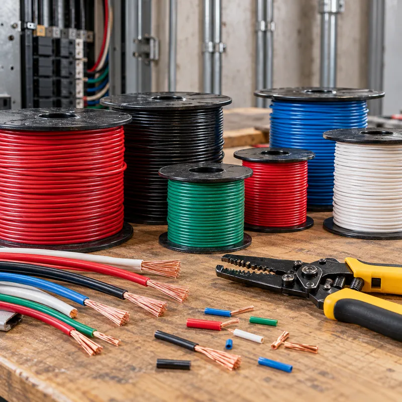
In AWG, smaller numbers mean larger wire: 4 AWG is larger than 10 AWG. Above 4/0, sizes are in kcmil (thousand circular mils), and IEC markets use mm². For transformer-specific conductor selection, see the transformer wire selection and sizing guide.
Amps to Wire Size Chart (NEC Table 310.16)
The chart below reproduces commonly used NEC Table 310.16 ampacities for copper and aluminum, not more than three current-carrying conductors, 30°C ambient. Columns: 60°C (TW, UF), 75°C (THWN, XHHW), 90°C (THHN, THWN-2, XHHW-2, mainly as the derating base).
| Size | Cu 60°C | Cu 75°C | Cu 90°C | Al 75°C | Al 90°C |
|---|---|---|---|---|---|
| 14 AWG | 15 | 20 | 25 | — | — |
| 12 AWG | 20 | 25 | 30 | 20 | 25 |
| 10 AWG | 30 | 35 | 40 | 30 | 35 |
| 8 AWG | 40 | 50 | 55 | 40 | 45 |
| 6 AWG | 55 | 65 | 75 | 50 | 55 |
| 4 AWG | 70 | 85 | 95 | 65 | 75 |
| 3 AWG | 85 | 100 | 115 | 75 | 85 |
| 2 AWG | 95 | 115 | 130 | 90 | 100 |
| 1 AWG | 110 | 130 | 145 | 100 | 115 |
| 1/0 | 125 | 150 | 170 | 120 | 135 |
| 2/0 | 145 | 175 | 195 | 135 | 150 |
| 3/0 | 165 | 200 | 225 | 155 | 175 |
| 4/0 | 195 | 230 | 260 | 180 | 205 |
| 250 kcmil | 215 | 255 | 290 | 205 | 230 |
| 350 kcmil | 260 | 310 | 350 | 250 | 280 |
| 500 kcmil | 320 | 380 | 430 | 310 | 350 |
Two rules limit how the chart is used. NEC 240.4(D) caps overcurrent protection for small copper conductors at 15 A for 14 AWG, 20 A for 12 AWG and 30 A for 10 AWG. NEC 110.14(C) requires circuits of 100 A or less, or 14 through 1 AWG conductors, to use the 60°C column unless all terminations are listed for 75°C; above 100 A, the 75°C column applies. Most modern breakers and lugs are rated 75°C, but confirm on the equipment.
How to Calculate Cable Size: Step-by-Step Method
To calculate the cable size for a feeder or branch circuit, follow the sequence below. It is the logic built into any reputable online wire size calculator.
- Find design current. Single phase
I = P / (V × PF); three phaseI = P / (√3 × V × PF), or from kVA,I = S / (√3 × V). - Apply 125% for continuous loads (three hours or more) per NEC 210.19 and 215.2.
- Select by termination temperature. Size from the 60°C or 75°C column at the 125% value.
- Apply correction and adjustment. Use Table 310.15(B)(1) for ambient and 310.15(C)(1) for more than three current-carrying conductors: 80% for 4–6, 70% for 7–9, 50% for 10–20. The derated ampacity, normally from the 90°C column, must carry the actual load.
- Check voltage drop and upsize if needed.
- Select overcurrent protection not exceeding conductor ampacity, using standard ratings in 240.6.
- Size the grounding conductor from Table 250.122.
Worked example: 480 V feeder with derating
A 120 A continuous load, copper THHN, six current-carrying conductors in one conduit, 40°C ambient, 75°C terminals.
- Termination check:
1.25 × 120 = 150 A; 1/0 Cu at 75°C = 150 A. - Derating: factors 0.91 (40°C, 90°C insulation) × 0.80 (six conductors) = 0.728.
- 2 AWG:
130 × 0.728 = 94.6 A, too small. 1/0:170 × 0.728 = 123.8 A, which carries 120 A. - Result: 1/0 copper on a 150 A breaker.
Had the insulation been rated only 75°C, the derating would apply to the 75°C column (0.88 × 0.80) and 2/0 would be needed.
Wire Size Breaker Size Chart and Service Entrance Sizes
The chart pairs common breaker ratings with the minimum conductor at the 75°C column, assuming non-continuous load or a load already multiplied by 125%, no derating and 75°C terminals. It answers frequent questions such as 100 amp wire size and wire gauge for 80 amps.
| Breaker | Copper | Aluminum | Notes |
|---|---|---|---|
| 15 A | 14 AWG | 12 AWG | 240.4(D) limit |
| 20 A | 12 AWG | 10 AWG | 240.4(D) limit |
| 30 A | 10 AWG | 8 AWG | 240.4(D) limit |
| 40 A | 8 AWG | 8 AWG | 60°C terminals: 8 Cu, 6 Al |
| 60 A | 6 AWG | 4 AWG | 60°C terminals: 4 Cu |
| 80 A | 4 AWG | 2 AWG | 60°C terminals: 3 Cu |
| 100 A | 3 AWG | 1 AWG | 60°C terminals: 1 Cu, 1/0 Al |
| 150 A | 1/0 | 3/0 | 75°C column applies |
| 200 A | 3/0 | 250 kcmil | 75°C column applies |
| 400 A | 2 × 3/0 or 600 kcmil | 2 × 250 kcmil | Parallel sets 1/0 and larger |
Service entry wire size chart for dwellings
For a 120/240 V single-phase dwelling service or main feeder carrying the entire load, NEC 310.12 permits sizing at 83% of the service rating. Table 310.12 gives, for example, 4 AWG copper or 2 AWG aluminum for 100 A, 2/0 copper or 4/0 aluminum for 200 A, and 400 kcmil copper or 600 kcmil aluminum for 400 A. This allowance does not apply to commercial or three-phase services. Service work must be done by a licensed electrician under the locally adopted code.
For breaker selection on transformer primaries and secondaries, see the transformer breaker size chart.
Voltage Drop: When Distance Sets the Conductor Size
Ampacity alone ignores length. For copper at 75°C the resistivity constant is K ≈ 12.9 Ω·cmil/ft, and for aluminum K ≈ 21.2. The voltage drop formulas are:
- Single phase:
VD = 2 × K × I × L / cmil - Three phase:
VD = √3 × K × I × L / cmil - Minimum area for a target drop:
cmil = 2 × K × I × L / VD(single phase)
L is one-way length in feet. Circular mil areas: 6 AWG 26,240; 4 AWG 41,740; 2 AWG 66,360; 1 AWG 83,690; 1/0 105,600; 4/0 211,600.
Example 1: 240 V, 60 A, 150 ft
6 AWG copper (65 A) passes ampacity. VD = 2 × 12.9 × 60 × 150 / 26,240 = 8.85 V, or 3.7%. Upsizing to 4 AWG: 5.56 V, 2.3%, within the 3% recommendation.
Example 2: 480 V three phase, 100 A continuous, 250 ft
125% gives 125 A, so 1 AWG copper (130 A). VD = 1.732 × 12.9 × 100 × 250 / 83,690 = 6.67 V, 1.4%. Acceptable.
For large conductors use NEC Chapter 9 Table 9 impedance: VD = √3 × I × L × (R cos φ + X sin φ); the simple K method understates drop at low power factor. Basic Ohm's law relationships behind these formulas are in how to calculate voltage.
When the phase conductors are upsized for voltage drop, NEC 250.122(B) requires the equipment grounding conductor to be increased proportionally by circular mil area.
Wire Sizing for Motors and Generators
Motor and generator circuits follow their own NEC articles rather than the general continuous-load rule.
Motors (Article 430)
Branch-circuit conductors for a single motor must have ampacity of at least 125% of the full-load current from NEC Tables 430.247–430.250, not the nameplate current (430.6 and 430.22). Overloads use the nameplate current.
Example: a 50 hp, 460 V three-phase induction motor has a Table 430.250 FLC of 65 A. 1.25 × 65 = 81.3 A, so 4 AWG copper at 75°C (85 A). Check long runs for starting voltage drop. Current calculations from kW and hp are covered in full load amps calculator.
Generators (Article 445)
Conductors from generator terminals to the first overcurrent device must have ampacity of at least 115% of the nameplate current rating under NEC 445.13.
Example: a 125 kVA, 480 V standby generator. I = 125,000 / (1.732 × 480) = 150.4 A; 1.15 × 150.4 = 173 A, so 2/0 copper (175 A). Generator selection itself is covered in the generator sizing guide.
Transformer secondaries
Secondary conductors from a transformer often run without overcurrent protection at the transformer and are governed by the tap rules in NEC 240.21(C). Size them on the secondary full-load current, I = kVA × 1,000 / (√3 × V); a 500 kVA, 480 V secondary carries 601 A, typically two parallel sets of 350 kcmil copper (2 × 310 = 620 A).
Grounding Wire Size: A Quick Rule
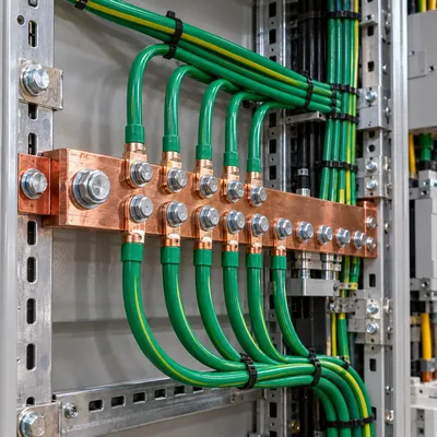
A grounding wire size calculator does not use ampacity at all. The equipment grounding conductor (EGC) is sized from the rating of the overcurrent device ahead of the circuit, using NEC Table 250.122, because it must carry fault current only long enough to trip that device.
- Up to 20 A: 12 AWG copper (14 AWG on 15 A).
- 60 A: 10 AWG copper; 100 A: 8 AWG copper; 200 A: 6 AWG copper.
- 400 A: 3 AWG copper; 800 A: 1/0 copper.
The grounding electrode conductor at a service or transformer is a different conductor, sized from the service or secondary conductor area with Table 250.66. The full tables, parallel-run rules, transformer bonding and worked examples are in the equipment grounding conductor sizing guide.
In IEC practice, earthing cable size is usually chosen from IEC 60364-5-54 from a table based on phase size (equal up to 16 mm², 16 mm² for 16–35 mm², half above 35 mm²) or by the adiabatic equation S = √(I² × t) / k.
Medium Voltage and HV Cable Sizing
For 2.4 kV to 35 kV cables, NEC Article 311 and its ampacity tables cover North American practice, while IEC 60502-2 cable construction and IEC 60287 rating calculations govern most other markets. A medium voltage cable sizing calculator accounts for installation method, soil thermal resistivity, grouping and screen bonding.
At MV, load current is often small relative to cable capability, and the decisive check is short-circuit withstand. The adiabatic equation gives the minimum area:
S = I × √t / k, with S in mm², I in A, t in seconds, and k = 143 for copper XLPE (90°C to 250°C), 94 for aluminum XLPE.
Worked example: 1,600 kVA transformer feeder at 11 kV
- Load current:
1,600,000 / (1.732 × 11,000) = 84 A. A 35 mm² copper XLPE cable would carry this easily. - Fault level at the switchgear: 20 kA for 0.5 s backup clearing.
S = 20,000 × √0.5 / 143 = 98.9 mm², so 120 mm² copper is required.- Check screen fault rating separately for earth-fault current.
MV system voltages and insulation levels are compared in the medium voltage power systems guide.
Next Steps: Specifying and Sourcing
Cable sizes and transformer ratings are interdependent: transformer impedance sets fault current, which sets MV and LV cable withstand, and secondary voltage sets current and therefore conductor size. In a transformer or substation RFQ, state:
- kVA rating, primary and secondary voltages, and percent impedance target.
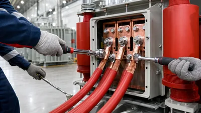
- Number and size of incoming and outgoing cables per phase, so bushings, lugs and cable boxes can accept them.
- Conductor material (copper or aluminum) and termination type: compression lugs, bolted, or separable connectors.
- Upstream fault level and protection clearing time for short-circuit checks.
- Cable entry direction: top, bottom or side, and gland plate requirements.
MARS supplies oil-immersed transformers and compact substations with cable terminations designed around the customer's cable schedule. Share your cable schedule on the quote request page for a coordinated offer.
Frequently asked questions
What size wire do I need for 100 amps?
With 75°C rated terminals, 3 AWG copper or 1 AWG aluminum per NEC Table 310.16. If the equipment terminals are rated only 60°C, use 1 AWG copper or 1/0 aluminum. A dwelling service carrying the entire load may use 4 AWG copper or 2 AWG aluminum under NEC 310.12. Long runs may need upsizing for voltage drop.
What wire gauge is needed for 80 amps?
For an 80 A circuit with 75°C terminations, 4 AWG copper (85 A) or 2 AWG aluminum (90 A). With 60°C terminations, 3 AWG copper is required. If the load is continuous, size for 125% of the load current first, then select the breaker and conductor.
How do you calculate wire size for amps?
Determine load current, multiply by 1.25 for continuous loads, and select a conductor from NEC Table 310.16 in the column matching the termination temperature. Apply ambient and bundling correction factors, then check voltage drop over the run length and upsize if the drop exceeds about 3%.
How do I size a wire for a motor?
Use the full-load current from NEC Table 430.250 for three-phase motors, not the nameplate, and multiply by 125%. A 50 hp, 460 V motor has a table FLC of 65 A, so conductors need at least 81 A ampacity, which is 4 AWG copper at 75°C.
What size wire do I need from a generator?
Conductors from the generator to the first overcurrent device must be rated at least 115% of the generator nameplate current under NEC 445.13. A 125 kVA, 480 V generator produces 150 A, so the conductors need 173 A ampacity, which is 2/0 copper at 75°C.
How are medium voltage cables sized?
MV cables are checked for continuous current under installation conditions using IEC 60287 or NEC Article 311, and for short-circuit withstand using S = I√t/k. On transformer feeders the short-circuit check usually governs, giving a larger cross-section than load current alone requires.
Written and reviewed by the MARS application engineering team in Shanghai, who specify and test transformers, switchgear, substations and battery storage for projects in 40+ countries. Last updated .
Tags: wire size calculator amps to wire size wire size breaker size chart calculate cable sizing medium voltage cable sizing calculator