Key takeaways
- Ohm's law V = I × R links volts, amperes and ohms; one ohm is the resistance that passes one ampere when one volt is applied.
- In a series circuit total voltage equals the sum of the individual drops, so 2 Ω, 4 Ω and 6 Ω on 12 V drop 2, 4 and 6 V.
- Power equals voltage times current, P = V × I, which also gives P = I²R and P = V²/R by substituting Ohm's law.
- AC circuits use V = I × Z, where impedance Z = √(R² + X²) and inductive reactance X_L = 2πfL depends on frequency.
- Transformer secondary voltage follows the turns ratio, V₂ = V₁ × N₂ / N₁, before load-dependent voltage regulation is applied.
Quick answer: To calculate voltage, multiply current by resistance: V = I × R (Ohm's law). If you know power instead, use V = P / I or V = √(P × R). In a series circuit the total voltage is the sum of each drop; in parallel every branch has the same voltage. For AC, replace R with impedance Z.
Almost every electrical calculation starts with the same three quantities: voltage, current and resistance. Whether you are checking a control circuit, estimating voltage drop on a feeder or confirming the output of a distribution transformer, the method is to identify what is known and rearrange one of a handful of basic formulas to solve for what is not.
This guide is for technicians, students and engineers who want those formulas in one place with clear examples. It starts with definitions and Ohm's law, works through series and parallel circuits, adds the power equations, then extends them to AC impedance, three-phase systems and transformers, where the same rules scale up to megawatts.
Definition of Voltage, Current and Resistance
Voltage is the electrical potential difference between two points, the energy given to each coulomb of charge, measured in volts (V). One volt equals one joule per coulomb. Current is the rate of flow of charge, measured in amperes (A), where one ampere is one coulomb per second. Resistance is the opposition a material offers to current, measured in ohms (Ω).
A useful picture is water in a pipe: voltage is pressure, current is flow rate, and resistance is the narrowness of the pipe. The analogy breaks down for AC and magnetic effects, but it explains why more pressure or a wider pipe produces more flow.
Volts vs ohms: why they are not interchangeable
Searches for volts to ohms or ohms vs volts often come from confusion between cause and property. Voltage is something a source applies; resistance is a property of the conductor or load. You cannot convert one into the other without knowing the current. If 12 V drives 3 A through a lamp, its resistance at that operating point is 12 / 3 = 4 Ω. Change the voltage and, for a lamp filament, the resistance changes too because it depends on temperature.
| Quantity | Symbol | Unit | Defined as |
|---|---|---|---|
| Voltage | V or E | volt (V) | joule per coulomb |
| Current | I | ampere (A) | coulomb per second |
| Resistance | R | ohm (Ω) | volt per ampere |
| Power | P | watt (W) | joule per second, volt × ampere |
| Impedance | Z | ohm (Ω) | AC volts per AC ampere |
How Do You Calculate Voltage with Ohm's Law?
Ohm's law states that the current through a linear conductor is proportional to the voltage across it. In its three arrangements:
V = I × R: voltage is equal to current times resistance.I = V / R: current is voltage divided by resistance.R = V / I: resistance is voltage divided by current.
So what is an ohm equal to? One ohm is one volt per ampere. A 1 Ω resistor passes 1 A when 1 V is applied, and 10 A when 10 V is applied.
Steps to solve for voltage
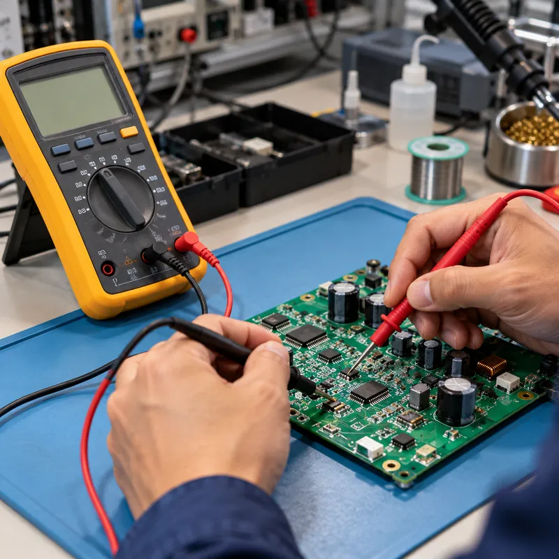
- Identify the two points between which voltage is wanted.
- Find the current flowing between them and the resistance in that path.
- Convert units to base values: milliamps to amps, kilohms to ohms.
- Multiply:
V = I × R. - Check the answer is plausible against the supply voltage.
Example: a 4–20 mA instrument loop has a 250 Ω sense resistor. At 12 mA, the voltage across it is 0.012 × 250 = 3.0 V. At 20 mA it is 5.0 V, which is why 250 Ω resistors convert loop signals to a 1–5 V range.
Ohm's law holds for metallic conductors at a steady temperature. It does not describe diodes, arcs or saturated iron cores, which are nonlinear. For practical engineering, the conductors and resistors in power circuits behave linearly enough to use it directly, with resistance corrected for operating temperature.
Voltage in Series Circuits: How to Calculate Total Voltage
In a series circuit there is only one path, so the same current flows through every element. Kirchhoff's voltage law says the sum of voltage drops around a loop equals the applied voltage. The series voltage formula is therefore V_total = V₁ + V₂ + V₃ + …, and total resistance is R_total = R₁ + R₂ + R₃ + ….
Worked example
A 12 V supply feeds 2 Ω, 4 Ω and 6 Ω in series.
R_total = 2 + 4 + 6 = 12 ΩI = 12 / 12 = 1.0 A- Drops:
V₁ = 1 × 2 = 2 V,V₂ = 4 V,V₃ = 6 V - Check:
2 + 4 + 6 = 12 V
The voltage divider rule shortcuts this: the drop across any element is V_x = V_total × R_x / R_total. The 6 Ω resistor drops 12 × 6 / 12 = 6 V.
Sources in series add too. Four 12 V batteries in series give 48 V, which is how battery strings reach useful voltages; large LFP systems connect hundreds of 3.2 V cells in series to reach 700–1,500 V DC. If one source is reversed, its voltage subtracts.
What is the total voltage of the circuit when you only know the drops? Add them. When you know the supply, measure or calculate the drops and confirm they sum to it; a missing difference points to a hidden resistance such as a loose terminal or a corroded joint.
Voltage in Series and Parallel: Formula Comparison
In a parallel circuit every branch connects across the same two nodes, so every branch has the same voltage while currents add. Total resistance falls below the smallest branch: 1 / R_total = 1 / R₁ + 1 / R₂ + …, or for two resistors R_total = R₁ × R₂ / (R₁ + R₂).
| Rule | Series | Parallel |
|---|---|---|
| Voltage | Divides: V_total = ΣV | Same across all branches |
| Current | Same everywhere | Adds: I_total = ΣI |
| Resistance | R_total = ΣR | 1/R_total = Σ(1/R) |
| One element opens | Whole circuit stops | Other branches continue |
| Typical use | Divider, battery strings, current loops | Building loads, outlets, feeders |
Parallel example: 6 Ω and 3 Ω in parallel on 12 V. Each sees 12 V; currents are 2 A and 4 A; total 6 A; R_total = 18 / 9 = 2 Ω, and 12 / 2 = 6 A confirms it.
Real installations combine both. Building loads are wired in parallel across the supply, but the feeder cable is in series with them, so the cable's resistance causes a voltage drop that every load shares. That drop is the reason conductor sizing goes beyond ampacity, as explained in the wire size calculator guide.
Power Equals Voltage Times Current: The Power Voltage Equation
Electrical power is the rate of energy transfer. In DC and resistive circuits, power equals voltage times current: P = V × I. Substituting Ohm's law gives two more forms, together called the power wheel:
P = I² × R, used for conductor and winding losses.P = V² / R, power in terms of voltage and resistance, used for heaters.
Rearranged for voltage: V = P / I and V = √(P × R).
| Unknown | From V and I | From I and R | From V and R | From P and… |
|---|---|---|---|---|
| V | — | I × R | — | P / I or √(P × R) |
| I | — | — | V / R | P / V or √(P / R) |
| R | V / I | — | — | V² / P or P / I² |
| P | V × I | I² × R | V² / R | — |
Worked example: 240 V water heater
A 4.8 kW element on 240 V draws I = 4,800 / 240 = 20 A; its resistance is R = 240² / 4,800 = 12 Ω. On a 208 V supply the same element produces 208² / 12 = 3,605 W, 25% less, because power varies with the square of voltage. That square-law effect explains why voltage choice matters so much when replacing transformers, a topic covered in 208 vs 240 volts.
How to Find Voltage in AC and Three-Phase Circuits
In AC circuits, inductors and capacitors oppose current through reactance as well as resistance. Ohm's law becomes V = I × Z, with impedance Z = √(R² + X²), inductive reactance X_L = 2πfL and capacitive reactance X_C = 1 / (2πfC). Because reactance depends on frequency f, the same coil draws 20% more current at 50 Hz than at 60 Hz, as explained in 50 Hz vs 60 Hz.
Voltage and amperage in AC are usually quoted as RMS values. A 120 V RMS sine wave peaks at 120 × √2 = 170 V. Meters labelled true-RMS read correctly on distorted waveforms.
Power in AC adds the power factor: P = V × I × PF for single phase and P = √3 × V_L × I_L × PF for three phase. The meaning of PF and the full power triangle are covered in power factor explained and apparent, reactive and real power.
Three-phase voltage
In a wye system, line-to-line voltage is √3 times line-to-neutral: 277 V × 1.732 = 480 V. To find an unknown supply voltage from load data, rearrange the three-phase power equation: V_L = P / (√3 × I × PF). Example: a motor draws 52 A at 0.86 PF while taking 37 kW; V_L = 37,000 / (1.732 × 52 × 0.86) ≈ 478 V, consistent with a 480 V system.
Voltage drop on a feeder
For three-phase feeders, VD = √3 × I × L × (R cos φ + X sin φ), where R and X are per-unit-length conductor values. This form captures the reactive part that the simple I × R estimate misses on large cables.
How to Calculate Transformer Voltage
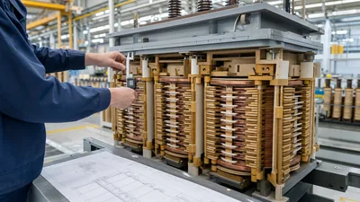
A transformer's no-load secondary voltage follows its turns ratio: V₂ = V₁ × N₂ / N₁. The EMF equation behind it is E = 4.44 × f × N × A × B_max, linking voltage to frequency, number of turns, core area and peak flux density.
Worked example
A 13,800 V to 480 V transformer has a line voltage ratio of 13,800 / 480 = 28.75. If the utility delivers 13,455 V, 2.5% low, the secondary falls to 13,455 / 28.75 = 468 V at no load. Moving the off-circuit tap changer to the −2.5% position reduces primary turns and restores 480 V.
Under load, the secondary drops further by the regulation, approximately %Reg ≈ %R × cos φ + %X × sin φ for a transformer with known percent resistance and reactance. A unit with 1.0% R and 5.5% X at 0.85 PF lagging regulates by about 1.0 × 0.85 + 5.5 × 0.53 ≈ 3.8%, so 480 V at no load becomes about 462 V at full load.
These are the same electricity calculation formulas used for small circuits, applied to windings with thousands of turns. For turns, core and winding calculations in more detail, see the transformer winding calculator guide, and for regulation and tap selection the voltage regulation guide.
Next Steps: Specifying and Sourcing
When your calculations move from a bench circuit to a site supply, the voltage numbers become specification items. For a transformer RFQ, state:
- Primary nominal voltage, its expected range and system frequency.
- Secondary voltage as line-to-line and line-to-neutral values, for example 400/230 V or 480Y/277 V.
- Tap range and step, typically ±2 × 2.5% off-circuit, or an on-load tap changer for wide variation.
- Target impedance and maximum acceptable regulation at the expected power factor.
- Large motor starting loads and permissible voltage dip.
- Applicable standard: IEC 60076, IEEE C57.12.00 or GB.
MARS builds oil-immersed transformers and cast-resin dry-type transformers to customer voltage, tap and impedance requirements, with routine ratio, resistance and impedance tests on every unit. Send your data via the quote request page for a technical and commercial proposal.
Frequently asked questions
How do you find voltage if you know current and resistance?
Multiply them: V = I × R. A current of 2.5 A through a 48 Ω resistor produces 2.5 × 48 = 120 V across it. Convert milliamps to amps and kilohms to ohms before multiplying, otherwise the result will be off by a factor of a thousand.
How do you calculate total voltage in a series circuit?
Add the voltage drops across every element: V_total = V₁ + V₂ + V₃. Equivalently, find the circuit current from I = V/R_total and multiply by each resistance. The drops always add up to the source voltage, according to Kirchhoff's voltage law, so a shortfall indicates an unaccounted resistance.
Is voltage the same in series or parallel?
Voltage is the same across every branch of a parallel circuit. In a series circuit the current is the same through every element, and the total voltage divides between them in proportion to their resistance. Household and building loads are connected in parallel so each receives full supply voltage.
How do you calculate voltage from power and current?
Divide power by current: V = P / I. A 1,500 W heater drawing 12.5 A operates at 1,500 / 12.5 = 120 V. In AC circuits with reactive loads, include power factor: V = P / (I × PF) for single phase and V = P / (√3 × I × PF) for three phase.
What is the relationship between volts, amps and ohms?
Ohm's law: volts equal amps times ohms. Increasing voltage across a fixed resistance raises current proportionally; increasing resistance at fixed voltage lowers current. One ohm is the resistance that allows one ampere to flow when one volt is applied across it.
How do you calculate voltage with power and resistance?
Use V = √(P × R). A heating element rated 2,000 W with a resistance of 28.8 Ω operates at √(2,000 × 28.8) = √57,600 = 240 V. This form is useful when only the nameplate power and a measured cold or hot resistance are available.
Written and reviewed by the MARS application engineering team in Shanghai, who specify and test transformers, switchgear, substations and battery storage for projects in 40+ countries. Last updated .
Tags: how to calculate voltage voltage in series volts amperes and ohms power equals voltage times current electricity basic formulas