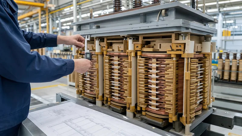
Key takeaways
- The core electromagnetic relationship relies on the formula E = 4.44 × f × Bmax × Ae × N, dictating the required turns per volt.
- Grain-oriented silicon steel cores are typically designed for peak flux densities between 1.60 and 1.75 Tesla to avoid core saturation under overvoltage conditions.
- Current density for natural oil-cooled (ONAN) distribution windings is typically selected between 2.0 and 3.2 A/mm² to maintain standard thermal rise limits.
- Low-voltage secondary windings must use an integer number of turns per phase, which subsequently defines the precise turns-per-volt ratio for the primary winding.
- Accurate coil calculations require factoring in window fill factors between 0.25 and 0.40 to accommodate conductor enamel, interlayer kraft paper, and cooling ducts.
Quick answer: A transformer winding calculator determines the required primary and secondary turns, conductor cross-sectional areas, and window space allocation based on the operating frequency, voltage rating, core cross-sectional area, and design magnetic flux density. The calculation uses the fundamental electromotive force equation: turns per volt equals 1 divided by (4.44 × frequency × magnetic flux density × core effective area).
Designing an electrical transformer requires a balance between electromagnetic performance, thermal dissipation, mechanical strength during short circuits, and material efficiency. Whether designing a small isolation unit, a standard three-phase distribution transformer, or a medium-power unit, manual calculation or computerized automation requires the same physics-based methodology. When determining parameters using a transformer coil calculator, an electrical engineer must ensure the magnetic core does not saturate at maximum operating voltage while keeping the winding resistance low enough to satisfy guaranteed load loss figures.
Deviations in coil geometry or inadequate conductor cross-sections lead to excessive I²R losses, elevated hotspot temperatures, and reduced operational lifespan. To understand how thermal ratings relate to transformer lifespan, refer to our detailed transformer winding temperature guide. This guide breaks down the core equations, conductor sizing parameters, empirical fill factors, and practical steps needed to build an accurate winding calculation routine.
Electromagnetic Principles Behind the Transformer Winding Calculator
The foundation of every transformer winding calculation rests on Faraday's Law of Electromagnetic Induction as applied to alternating magnetic circuits. The induced root-mean-square (RMS) electromotive force (EMF), denoted as E, induced in an alternating current winding is expressed by the standard formula:
E = 4.44 × f × Bmax × Ae × N
Where:
- E = Induced phase voltage (V RMS)
- f = Power system frequency in Hertz (typically 50 Hz or 60 Hz)
- Bmax = Maximum operating magnetic flux density in the core (Tesla, T)
- Ae = Effective magnetic cross-sectional area of the iron core (m²)
- N = Number of turns in the specific winding
By rearranging this fundamental equation, we derive the critical operational design metric known as turns per volt (TPV):
TPV = N / E = 1 / (4.44 × f × Bmax × Ae)
For cold-rolled grain-oriented (CRGO) silicon steel (such as grade M4 or high-permeability grades like 23ZH090), engineers generally limit Bmax to between 1.60 T and 1.72 T under normal operating voltage. Exceeding 1.75 T risks driving the core steel into magnetic saturation during routine system overvoltage conditions (governed by IEC 60076-1 clause 5.4, which permits continuous operation at 105% voltage). Core saturation creates high magnetising inrush currents, severe harmonic distortion, and excessive no-load core losses.
Step-by-Step Transformer Coil Calculator Methodology
Executing a coil calculation requires sequential evaluation of electrical, geometric, and thermal constraints. To systematically execute a transformer coil calculator routine for a single-phase or three-phase unit, apply the following procedure:
- Determine phase voltages and phase currents: Convert the rated apparent power (kVA) and line voltages to individual phase quantities based on the winding connection (Star or Delta). For Delta windings, phase voltage equals line voltage; for Star windings, phase voltage equals line voltage divided by √3. If converting line values, verify equations against our guide on conversion from ampere to kVA.
- Determine the effective core cross-sectional area (Ae): Calculate the gross physical core area multiplied by the core stacking factor (typically 0.95 to 0.97 for varnished laminated steel sheets) to establish the net active iron area.
- Calculate the turns per volt (TPV): Apply the operational frequency and chosen flux density Bmax to establish the TPV ratio using the rearranged EMF equation.
- Calculate secondary winding turns (Ns): Multiply the secondary phase voltage by the TPV. Because coils can only accommodate whole integer turns in standard concentric construction, round Ns to the nearest whole integer.
- Recalculate precise volts-per-turn (et): Recalculate et = Vphase_secondary / Ns. This adjusted parameter prevents voltage ratio errors when sizing the primary coil.
- Calculate primary winding turns (Np): Divide the primary phase voltage by the refined volts-per-turn value (Np = Vphase_primary / et). For distribution transformers, include tapping turns (typically ±2 × 2.5%) on the high-voltage winding.
- Size the conductor cross-section: Divide the continuous phase current by the target current density J (A/mm²) to find the minimum bare conductor cross-sectional area.
- Verify window space factor: Check that the combined physical cross-section of primary and secondary windings, along with insulation barriers, oil ducts, and winding clearances, does not exceed the core window area.
Worked Calculation: 250 kVA Three-Phase Distribution Transformer
To demonstrate the exact formulas used inside a transformer winding calculator, consider a standard step-down distribution transformer engineered to IEC 60076 standards with the following input parameters:
- Rated power: 250 kVA, three-phase, 50 Hz
- Primary line voltage: 11,000 V (11 kV), Delta connected
- Secondary line voltage: 415 V (no-load phase voltage = 415 / √3 = 239.6 V), Star connected
- Core configuration: Three-limb core, CRGO grade with Bmax = 1.65 T
- Core diameter: 175 mm, giving a net effective core area (Ae) of 0.0215 m² (215 cm²) after accounting for stepped stacking
- Target current density (J): 2.5 A/mm² for annealed electrolytic copper
Step 1: Volts per turn calculation
et = 4.44 × f × Bmax × Ae = 4.44 × 50 × 1.65 × 0.0215 = 7.876 V/turn
Step 2: Secondary winding turns (LV)
Ns(ideal) = Vph(LV) / et = 239.60 / 7.876 = 30.42 turns
Because partial turns cannot be used on a concentric limb without creating flux asymmetry, select Ns = 30 turns.
Adjusted volts per turn: et(actual) = 239.60 / 30 = 7.987 V/turn.
Step 3: Primary winding turns (HV)
Because the primary is Delta-connected, phase voltage equals line voltage (11,000 V):
Np = Vph(HV) / et(actual) = 11,000 / 7.987 = 1,377.26 turns
Round to 1,377 turns for the nominal 11 kV tap. For tapping stages of ±2 × 2.5%, the turns will vary by ±34 turns per step.
Step 4: Conductor sizing and current
Secondary phase current (Star):
ILV = (250 × 1000) / (√3 × 415) = 347.8 A
Conductor area required (Acu(LV)):
Acu(LV) = 347.8 A / 2.5 A/mm² = 139.12 mm²
This is typically wound as rectangular copper strip (e.g., two parallel conductors of 10 mm × 7 mm bare) or continuous copper foil across the axial height of the limb.
Primary phase current (Delta):
IHV_phase = Iline / √3 = [(250 × 1000) / (√3 × 11,000)] / √3 = 13.12 A / 1.732 = 7.58 A
Conductor area required (Acu(HV)):
Acu(HV) = 7.58 A / 2.5 A/mm² = 3.03 mm²
A round enamelled copper wire with a bare diameter of approximately 1.96 mm provides 3.02 mm² of cross-sectional area, matching the 2.5 A/mm² current density requirement.
Conductor Sizing, Current Density and Insulation Clearances
Selecting the conductor cross-section requires matching the current density to the cooling medium and transformer class. For natural mineral oil-immersed transformers (ONAN), design current densities typically range from 2.0 to 3.2 A/mm² for copper and 1.2 to 2.0 A/mm² for electrical grade aluminium (EC grade). In dry-type cast resin units (AN cooling), current densities are generally lower—between 1.2 and 2.2 A/mm² for copper—to prevent exceeding the thermal limits defined by IEC 60076-11.
The physical space required inside the core window must account for electrical insulation. Conductor dimensions expand significantly once coated with polyvinyl acetal enamel, paper wrapping, or Nomex tape. The window space factor (Kw)—defined as the ratio of pure copper conductor area to the total core window area—is typically only 0.25 to 0.40 in medium-voltage transformers. High-voltage coils require substantial dielectric barriers: oil ducts (typically 4 mm to 10 mm wide), pressboard cylinders between HV and LV windings, and phase-to-phase clearances conforming to IEEE C57.12.00 Table 5 insulation withstand standards. For single-phase arrangements, see our engineering guide to single-phase transformer design.
Winding Design Parameters Across Standard Transformer Ratings
The optimal selection of core flux density, volts per turn, and current density varies systematically with transformer power capacity. The following reference table outlines typical baseline coil parameters calculated for three-phase 50 Hz distribution transformers utilizing modern CRGO steel cores and copper conductors operating at continuous rated load.
| Rated Power (kVA) | Voltage Ratio (HV / LV) | Core Diameter (mm) | Nominal Flux Density (T) | Volts Per Turn (V/t) | HV Turns / Phase (Nominal) | LV Turns / Phase | Typical Current Density (A/mm²) |
|---|---|---|---|---|---|---|---|
| 50 kVA | 11,000 V / 415 V | 115 mm | 1.62 T | 3.35 V/t | 3,284 | 72 | 2.6 A/mm² |
| 100 kVA | 11,000 V / 415 V | 140 mm | 1.65 T | 5.05 V/t | 2,178 | 47 | 2.5 A/mm² |
| 250 kVA | 11,000 V / 415 V | 175 mm | 1.65 T | 7.99 V/t | 1,377 | 30 | 2.5 A/mm² |
| 500 kVA | 11,000 V / 415 V | 215 mm | 1.68 T | 12.35 V/t | 891 | 19 | 2.4 A/mm² |
| 1,000 kVA | 11,000 V / 415 V | 265 mm | 1.70 T | 18.90 V/t | 582 | 13 | 2.3 A/mm² |
| 1,600 kVA | 11,000 V / 415 V | 310 mm | 1.70 T | 25.80 V/t | 426 | 9 | 2.2 A/mm² |
| 2,500 kVA | 11,000 V / 415 V | 360 mm | 1.71 T | 35.10 V/t | 313 | 7 | 2.1 A/mm² |
As capacity increases, volts-per-turn figures rise significantly, reducing the required turn counts. However, this increases the physical cross-section of each conductor, demanding careful consideration of eddy current losses within the copper itself.
Practical Limitations: Fill Factor, Stray Losses, and Impedance
A purely theoretical calculation can produce coil designs that fail physical winding assembly or miss target percentage impedance (%Z). Software-based calculations must incorporate mechanical tolerances for winding tension, conductor corner radii, and thermal expansion margins. If winding dimensions expand by just 2% beyond tolerance, the completed coil assembly will not fit into the core window.
Furthermore, alternating leakage flux induces eddy currents inside heavy rectangular conductors. If single conductor strip thickness exceeds 3.0 mm in high-current low-voltage windings, axial and radial eddy currents rise rapidly, generating localized thermal hot spots. Designers prevent this by transposing multiple smaller insulated conductors in parallel or using continuously transposed cable (CTC). Additionally, the physical spacing between the high-voltage and low-voltage windings dictates the short-circuit leakage reactance. Conforming to specified percent impedance values (such as 4.0% for 250 kVA or 5.75% for 1,000 kVA per IEC 60076-5) requires iterative adjustments to coil height, radial build, and insulation gaps. Factory verification follows standardized testing methods, which are detailed in our manual on factory transformer testing procedures.
Next steps: specifying and sourcing
When specifying custom-wound transformers or submitting an inquiry for distribution equipment, provide complete design boundaries rather than just kVA ratings. Include nominal primary and secondary voltages, connection vector group (e.g., Dyn11, Ynd11), grid frequency, ambient temperature profile, and required percentage impedance. For critical installations, define winding conductor material (electrolytic copper or EC-grade aluminium), maximum permissible no-load and load loss levels (such as Ecodesign Tier 2 or DOE 2016 standards), and short-circuit withstand capabilities. Explore our engineered oil-immersed transformers and dry-type transformers, or submit your single-line diagrams directly through our technical transformer quotation portal.
Frequently asked questions
What is the formula used in a transformer winding calculator?
The primary formula used is E = 4.44 × f × Bmax × Ae × N, where E represents induced voltage, f is system frequency, Bmax is maximum core flux density, Ae is effective core cross-sectional area, and N is the number of turns.
How do you calculate turns per volt in a transformer coil calculator?
Turns per volt (TPV) is calculated as 1 divided by (4.44 × frequency × core flux density × effective core area). Dividing the target winding voltage by this value gives the required number of turns for that coil.
What flux density should I use when calculating transformer windings?
For cold-rolled grain-oriented (CRGO) laminated steel, flux density is typically selected between 1.60 and 1.72 Tesla. For non-oriented silicon steel cores, design limits are lower, generally between 1.2 and 1.4 Tesla to prevent excessive saturation.
What current density should be used for copper transformer windings?
Natural oil-immersed (ONAN) transformers typically operate at 2.0 to 3.2 A/mm² for copper conductors. Cast resin dry-type transformers use lower current densities, typically 1.2 to 2.2 A/mm², to satisfy thermal class temperature rise requirements.
Why does a transformer winding calculator require rounding the secondary turns?
Transformer coils can only accommodate whole integer turns per phase on concentric core limbs. Once secondary turns are rounded to an integer, the actual volts-per-turn value is recalculated to accurately determine primary turns and match the target turns ratio.
Tags: transformer winding calculator transformer coil calculator coil design turns per volt transformer sizing


