Key takeaways
- A single phase transformer steps alternating voltages up or down using mutual electromagnetic induction across a shared magnetic circuit without changing electrical frequency.
- Residential distribution relies primarily on split-phase 120/240 V secondary systems derived from centre-tapped single-phase distribution units conforming to IEEE C57.12.20.
- Utilities deploy three single phase power transformer units to form high-voltage three-phase substation banks where transport logistics, road clearance limits, or single-phase sparing economics preclude three-phase units.
- Transformer percent impedance (%Z) directly governs voltage regulation and fault current contribution, with standard distribution values typically designed between 1.8% and 3.5%.
- Procurement specifications must define the primary Basic Impulse Level (BIL), temperature rise limits according to IEC 60076-2 or IEEE C57.12.00, no-load and load loss guarantees, and terminal bushing configurations.
Quick answer: A single phase transformer is a static electromagnetic device that transfers alternating electrical energy between two circuits at the same frequency through mutual induction, altering voltage and current levels according to its core-to-winding turns ratio.
In electrical power networks, the single phase transformer serves as the fundamental building block for both low-voltage distribution and extra-high-voltage utility transmission. While commercial and industrial facilities operate predominantly on balanced polyphase networks, single-phase architectures supply millions of single-family residences, rural distribution spurs, railway traction catenaries, and critical municipal assets worldwide. Understanding the electrical design, core geometry, magnetic characteristics, and operational parameters of the single phase transformer is essential for network planners, substation engineers, and procurement teams aiming to balance capital expenditure with lifecycle efficiency.
Operating Principles and Fundamental Equations of the 1 Phase Transformer
A 1 phase transformer operates on Faraday's law of electromagnetic induction, which states that any change in magnetic flux linking a conductive circuit induces an electromotive force (EMF) across that circuit.
When an alternating voltage $V_1$ is impressed across the primary winding having $N_1$ turns, it establishes an alternating magnetising current. This current drives a time-varying magnetic flux $\Phi(t)$ through a laminated ferromagnetic core. The core confines the magnetic flux path, linking the primary turns to the secondary winding of $N_2$ turns with minimal flux leakage. The induced root-mean-square (RMS) EMF in each winding is governed by the standard transformer equation:
$$E = 4.44 \cdot f \cdot N \cdot \Phi_{\text{max}} = 4.44 \cdot f \cdot N \cdot B_{\text{max}} \cdot A_c$$
where $f$ is the system frequency in hertz (Hz), $N$ represents the turn count, $B_{\text{max}}$ is the peak magnetic flux density in tesla (T), and $A_c$ is the effective cross-sectional area of the iron core in square metres ($m^2$). In modern distribution equipment operating at 50 Hz or 60 Hz, cold-rolled grain-oriented (CRGO) silicon steels typically run at peak flux densities between 1.6 T and 1.75 T to prevent magnetic saturation under nominal excitation.
Under ideal conditions where winding resistance, core losses, and leakage reactances are negligible, the transformation turns ratio $a$ relates terminal voltage, induced EMF, and winding currents:
$$a = \frac{V_1}{V_2} = \frac{N_1}{N_2} = \frac{I_2}{I_1}$$
Real-world apparatus deviates from this ideal model due to no-load losses (hysteresis and eddy currents in the core laminations) and load losses ($I^2R$ copper losses and stray load losses in the conductors and structural steelwork). Evaluating these losses according to IEC 60076-1 clause 5.4 or IEEE C57.12.00 Table 5 allows engineers to accurately calculate operational thermal performance, total cost of ownership (TOC), and cooling configurations. For a deeper analysis of ratings, see our guide on how transformers are rated.
Core and Winding Construction: Core-Type vs Shell-Type Architectures
The mechanical and magnetic performance of a single-phase unit depends directly on whether the assembly utilises a core-type or shell-type magnetic circuit.
In a core-type transformer, the magnetic core forms a continuous rectangular frame with two vertical limbs (legs) connected by horizontal top and bottom yokes. The primary and secondary windings are divided into two equal parts and wound concentrically on both vertical limbs. The low-voltage (LV) winding is positioned closest to the core steel to minimise dielectric insulation requirements, while the high-voltage (HV) winding sits concentrically over the LV winding, separated by an insulating cylinder and cooling duct. This layout simplifies repair, permits natural thermosiphon cooling oil circulation, and is standard for medium-voltage utility distribution equipment.
In a shell-type transformer, the core surrounds the electrical windings. The core has a three-limb magnetic circuit where the central limb has twice the cross-sectional area of each outer limb. The magnetic flux divides equally between the two outer limbs, meaning each return leg requires only 50% of the cross-sectional area. Windings are typically manufactured as pancake-style coils or interleaved discs, where HV and LV sections sandwich together along the central core leg. Shell-type units offer superior mechanical bracing against electromagnetic forces during through-fault conditions, making them ideal for heavy industrial applications, furnace supplies, and high-shock environments.
Conductor selection determines thermal limits and footprint. Small control transformers utilise round enameled copper magnet wire, while medium-to-large single-phase units use rectangular copper or electrical-grade aluminium conductors insulated with thermally upgraded kraft paper, aramid paper, or polyester film according to IEC 60085 thermal classes (105°C Class A, 120°C Class E, or 155°C Class F).
Single Phase Transformer Configurations: Distribution, Pad-Mounted, and Substation Equipment
Single-phase transformers are manufactured across three primary mechanical configurations depending on environmental conditions, network topology, and mechanical mounting requirements.
Pole-mounted units, standard throughout North America, Latin America, and Australasia, mount directly to wooden, concrete, or steel utility poles via welded mounting brackets complying with IEEE C57.12.20. These oil-immersed cylindrical tanks range from 5 kVA to 500 kVA, stepping primary medium voltages (such as 7.2 kV, 12.47 kV, or 34.5 kV line-to-ground) down to low utilisation voltages. They feature single or dual primary HV porcelain or composite bushings, tank ground lugs, internal expulsion fuses, and external surge arresters. For detailed wiring diagrams, refer to our single phase pole mounted transformer wiring guide.
Pad-mounted single-phase units are housed in tamper-resistant, weatherproof green-painted steel enclosures engineered for ground-level installation on concrete pads in underground residential distribution (URD) zones. Designed to ANSI C57.12.28 enclosure integrity requirements, these units separate dead-front high-voltage and low-voltage compartments behind lockable, shielded doors. The high-voltage compartment features 200 A loadbreak bushing wells and elbow connectors suited for loop-feed or radial underground cable configurations.
Industrial control and dry-type single-phase units are vacuum-pressure impregnated (VPI) or cast resin units installed indoors inside motor control centres (MCCs), switchgear cubicles, or plant enclosures. They deliver galvanically isolated secondary control power (typically 120 V AC or 24 V AC) from 480 V or 415 V supply lines, safeguarding automation electronics from mains line disturbances.
Selecting a Single Phase Transformer for Home and Residential Distribution
A single phase transformer for home networks uses a split-phase, three-wire secondary winding to supply two different domestic voltage levels simultaneously from a single magnetic core.
The secondary winding produces 240 V between the outer line conductors (L1 and L2). A centre-tap connection serves as the grounded system neutral (N). As a result, 120 V is available between either line conductor and the neutral point (line-to-neutral) for standard plug-in domestic appliances, lighting, and entertainment systems. Heavy household loads—including electric vehicle (EV) supply equipment (Level 2 chargers), ducted heat pumps, electric water heaters, and induction hobs—connect line-to-line across L1 and L2 to exploit 240 V. This split-phase architecture halves the required load current for high-power appliances, reducing circuit breaker ratings, cable copper cross-sectional areas, and distribution $I^2R$ power losses.
Engineers sizing residential distribution assets must evaluate diversified peak demand rather than simply summing connected loads. Residential load calculations follow national installation standards, such as NFPA 70 (National Electrical Code) Article 220 or IEC 60364-3. In typical suburban subdivisions, a single 50 kVA or 75 kVA pad-mounted transformer serves between four and ten single-family detached homes based on a calculated coincidence (diversity) factor between 0.35 and 0.55. Installing an undersized transformer triggers severe core heating and accelerates insulation degradation (halving operating life for every 6°C to 8°C continuous thermal excursion over the nameplate winding rise limit), while gross oversizing elevates annual utility system standing losses due to continuous no-load core magnetisation.
Single Phase Power Transformer Banks in High-Voltage Grids
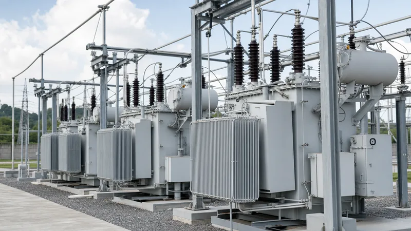
A single phase power transformer bank consists of three discrete single-phase units interconnected externally in star (wye) or delta configurations to operate as an ultra-high-capacity three-phase transformation node.
While large utilities typically deploy three-phase integrated units for distribution substations, transmission networks operating above 230 kV, 400 kV, and 765 kV frequently specify banks of three single-phase units for distinct technical and logistical reasons:
- Transport and Weight Envelopes: High-capacity power transformers exceeding 500 MVA reach shipping weights of 250 to 400 tonnes. Rail clearances, bridge structural capacities, and tunnel cross-sections often prohibit transporting a monolithic three-phase tank. Moving three identical single-phase units rated at 167 MVA each circumvents heavy haulage road routing restrictions.
- Substation Sparing Economics: In critical transmission substations feeding major industrial complexes or regional grids, an $N-1$ contingency policy requires continuous backup. Procuring a fourth identical single phase power transformer as a cold or hot on-site spare guarantees redundancy at roughly 33% of the equipment cost of an entire backup three-phase transformer.
- Custom Bushing and Core Geometry: Single-phase designs allow massive phase-to-ground clearances for ultra-high-voltage (UHV) bushings without enlarging the structural tank base or generating complex internal phase-to-phase dielectric clearance issues.
Engineers comparing three-phase designs against three-unit single-phase banks can review architectural trade-offs in our comprehensive 3 phase transformer engineering guide.
Worked Sizing Calculation and Electrical Parameter Table
Accurate transformer selection requires calculating nameplate kVA, nominal full-load current ($I_{\text{FL}}$), prospective secondary short-circuit current ($I_{\text{SC}}$), and percentage voltage drop under specified power factors.
Consider an engineering scenario: Sizing a pole-mounted single-phase distribution transformer feeding a rural commercial workshop and adjacent pumping station.
- Continuous connected load: 38 kVA
- Peak non-continuous motor starting load: 16 kVA
- Primary distribution supply voltage: 7,200 V AC, single-phase, 60 Hz
- Secondary utilisation voltage: 120/240 V AC, 3-wire split phase
- Operating load power factor (PF): 0.85 lagging
- Target maximum continuous loading: 80% of nameplate kVA
Step 1: Calculate Total Required kVA Rating
Applying a standard diversity factor of 0.85 to the combined continuous and starting demands:
$$S_{\text{design}} = (38 + [16 \cdot 0.70]) \cdot 0.85 = (38 + 11.2) \cdot 0.85 = 41.82 \text{ kVA}$$
Accounting for the 80% continuous design loading margin to provide thermal reserve and accommodate future load growth:
$$S_{\text{rating}} = \frac{41.82}{0.80} = 52.28 \text{ kVA}$$
The next standard preferred rating per IEEE C57.12.20 is 50 kVA (if diversity covers peak surges) or 75 kVA. Selecting a standard 50 kVA unit, verify actual continuous operation:
$$\text{Loading Factor} = \frac{38 \text{ kVA}}{50 \text{ kVA}} = 76\%$$
Step 2: Full-Load Current Calculation
On the 240 V line-to-line secondary terminals:
$$I_{\text{FL(secondary)}} = \frac{S}{V_2} = \frac{50,000 \text{ VA}}{240 \text{ V}} = 208.33 \text{ A}$$
On the 7,200 V primary terminal:
$$I_{\text{FL(primary)}} = \frac{50,000 \text{ VA}}{7,200 \text{ V}} = 6.94 \text{ A}$$
Step 3: Fault Level Calculation
Assuming a nameplate percentage impedance $(\%Z)$ of 2.1% (per standard IEEE C57 values) and an infinite primary bus:
$$I_{\text{SC}} = \frac{I_{\text{FL(secondary)}}}{\%Z / 100} = \frac{208.33}{0.021} = 9,920.5 \text{ A} \approx 9.92 \text{ kA}$$
Downstream main circuit breakers must feature an ultimate interrupting capacity (Icu) rated for at least 10 kA at 240 V AC. For complex network sizing, check our complete transformer sizing calculator guide.
The following table outlines technical specifications across standard distribution-class single-phase units:
| Rated Power (kVA) | HV Rating (V) | LV Rating (V) | Impedance %Z (%) | No-Load Loss (W) | Full-Load Loss (W) | Sound Level (dBA) |
|---|---|---|---|---|---|---|
| 15 | 7200 / 12470Y | 120/240 | 1.9 | 48 | 210 | 40 |
| 25 | 7200 / 12470Y | 120/240 | 2.0 | 68 | 320 | 42 |
| 37.5 | 7200 / 12470Y | 120/240 | 2.1 | 88 | 450 | 43 |
| 50 | 7200 / 12470Y | 120/240 | 2.1 | 105 | 580 | 45 |
| 75 | 7200 / 12470Y | 120/240 | 2.2 | 145 | 810 | 47 |
| 100 | 7200 / 12470Y | 120/240 | 2.3 | 180 | 1,040 | 48 |
| 167 | 7200 / 12470Y | 120/240 | 2.5 | 270 | 1,650 | 50 |
Testing, Factory Acceptance, and Commissioning Procedures
Factory Acceptance Testing (FAT) and field commissioning ensure that a newly installed single-phase unit meets design tolerances, dielectric strength standards, and loss guarantees before energisation.
Commissioning engineers should follow a structured sequence when validating equipment in the field:
- Visual and Mechanical Verification: Inspect external tank paint for transit scratches, check oil sight gauges for correct level, confirm that tank grounding terminals are bonded to the substation earth grid, and verify that bushing ceramic shed surfaces are clean and uncracked.
- Insulation Resistance (IR) Testing: Apply direct current (DC) test voltages using a calibrated megohmmeter (typically 2.5 kV or 5 kV DC for HV windings, 1 kV DC for LV windings) for 60 seconds to establish primary-to-secondary, primary-to-ground, and secondary-to-ground insulation resistance values. Acceptable readings should exceed 1,000 megohms at 20°C.
- Voltage Turns Ratio and Polarity Verification: Connect a turns ratio tester across HV and LV terminals to confirm the theoretical transformation ratio across all tap changer positions within the IEC ±0.5% tolerance band. Establish winding polarity (additive or subtractive) to prevent phase-opposition short circuits during parallel or bank connections.
- Winding Resistance Measurements: Measure winding DC resistance across all tap steps using a low-resistance digital ohmmeter (Kelvin bridge circuit). Convert values to reference temperature (75°C or 85°C) to verify mechanical connection integrity and rule out internal winding short circuits.
- Dielectric Liquid Breakdown Testing: For liquid-immersed transformers, draw an oil sample from the bottom sampling valve in accordance with IEC 60475. Test breakdown voltage per IEC 60156 or ASTM D877; dielectric breakdown voltage must exceed 30 kV for new untreated oil and 50 kV for processed insulating fluid.
Common Engineering Pitfalls and Specification Checklist
Specifying a transformer requires avoiding several recurring engineering errors that cause premature field failure, nuisance tripping, or excessive lifecycle expenses.
A critical oversight is failing to specify harmonic loading capability. Standard distribution transformers are engineered to deliver balanced sinusoidal currents. When feeding heavy non-linear modern loads—such as variable-frequency motor drives (VFDs), server computer power supplies, or large LED lighting arrays—triplen harmonics (3rd, 9th, 15th) induce high eddy current losses in the conductors and tank walls. If non-linear loads exceed 15% of the total rating, engineers must specify a single-phase unit with an appropriate K-factor rating (e.g., K-4, K-13) or derate standard equipment.
Another common mistake is misidentifying winding polarity during bank replacements. IEEE standards state that single-phase distribution transformers up to 200 kVA having primary voltage ratings up to 8,660 V possess additive polarity, whereas units outside those ratings exhibit subtractive polarity. Interconnecting units with opposite polarities into a three-phase bank produces an immediate short-circuit fault across the neutral line upon primary switch closure.
Before issuing a Request for Quotation (RFQ), verify the following specification parameters:
- Rated Capacity: kVA base rating and required future overload capacity (e.g., ONAN/ONAF ratings).
- System Voltages: Primary nominal voltage, basic impulse level (BIL, typically 60 kV to 150 kV for MV), and secondary open-circuit voltage.
- Winding Material: Electrolytic copper or electrical-grade aluminium windings based on lifecycle loss evaluations.
- Impedance (%Z): Specific nominal impedance with acceptable tolerance bands (±10% per IEC 60076-1).
- Fluid Type: Conventional mineral insulating oil (IEC 60296) or high-fire-point synthetic/natural ester fluid (IEC 62770) for enhanced fire safety.
- Corrosion Protection: Tank coating category per ISO 12944 (e.g., C3 for standard urban environments, marine-grade coating for coastal or marine conditions).
Next Steps: Specifying and Sourcing
Specifying the optimal transformer requires a balance between installation footprint, efficiency standards, thermal dissipation, and procurement lead times. Whether your project demands standard overhead pole-mounted transformers for rural electrification, tamper-proof pad-mounted transformers for commercial sites, or custom-engineered oil-immersed transformers for large distribution substations, accurate technical definitions ensure smooth procurement and commissioning.
To discuss your design parameters, evaluate total owning cost models, or request a complete technical proposal, submit your equipment single-line diagrams, ambient criteria, and loss limits via our transformer quotation request page.
Frequently asked questions
What is a single phase transformer used for?
A single phase transformer steps down distribution-level voltages to common utilisation voltages (such as 120 V or 240 V) for homes, rural networks, and light commercial buildings. It is also deployed in transmission substations where three single-phase units form high-voltage three-phase banks.
Can you run a single phase transformer on a three phase supply?
Yes, a single phase transformer can operate from a three-phase supply by connecting its primary winding across two phase conductors (line-to-line) or across one phase conductor and neutral (line-to-neutral). However, this creates a single-phase load that can introduce phase current unbalance onto the upstream three-phase system.
What is the difference between a single phase and three phase transformer?
A single phase transformer operates with a single alternating voltage waveform, using two conductors (or three in split-phase) across one magnetic circuit. A three-phase transformer contains three sets of windings linked through a shared three-limbed core, carrying three alternating waveforms shifted by 120 electrical degrees to deliver continuous, balanced industrial power.
How do you calculate the size of a single phase transformer for home use?
To calculate the size, sum the continuous electrical loads in volt-amperes (VA), add the largest motor or compressor starting surge, and apply diversity factors following electrical codes like NFPA 70. Divide the final diversified demand by the target operating loading percentage (typically 80%) to determine the required kVA nameplate rating.
Why do electric utilities use single phase transformers instead of three phase in rural areas?
Utilities deploy single-phase equipment in rural regions because single-phase overhead line construction requires only one or two medium-voltage conductors, significantly lowering line construction and pole infrastructure costs over long transmission distances where connected customer densities are low.
Tags: single phase transformer single phase power transformer 1 phase transformer single phase transformer for home


