Key takeaways
- A single-phase 25 kVA transformer delivers 104.2 A at 240 V and draws 3.47 A at 7,200 V, from I = kVA × 1000 / V.
- Overhead single-phase distribution transformers are covered by IEEE C57.12.20 in North America and IEC 60076 for 50 Hz markets.
- Low impedance, often around 1.5–2.5% at this size, gives 120/240 V secondary fault currents of roughly 4–7 kA at the transformer terminals.
- Completely self-protected (CSP) units add an internal primary weak-link fuse, a secondary breaker and a tank-mounted arrester to the basic design.
- IEEE C57.91 allows planned short-time overloads above 25 kVA on cool days or short peaks, based on hot-spot temperature and insulation ageing.
Quick answer: A 25 kVA transformer is most often a single-phase, oil-immersed pole-mounted distribution transformer that steps a utility primary such as 7,200 V down to 120/240 V. It delivers 104 A at 240 V and draws about 3.5 A on a 7.2 kV primary. One unit typically serves one large home or a few smaller homes, depending on load diversity.
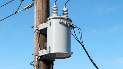
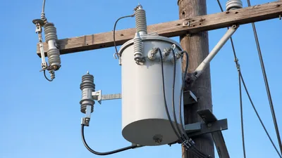
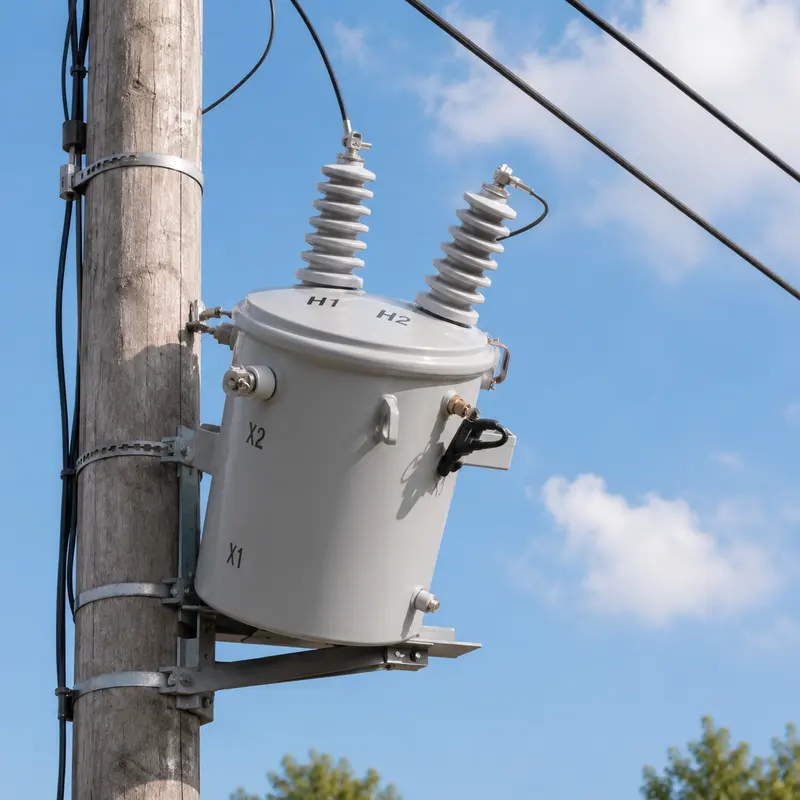
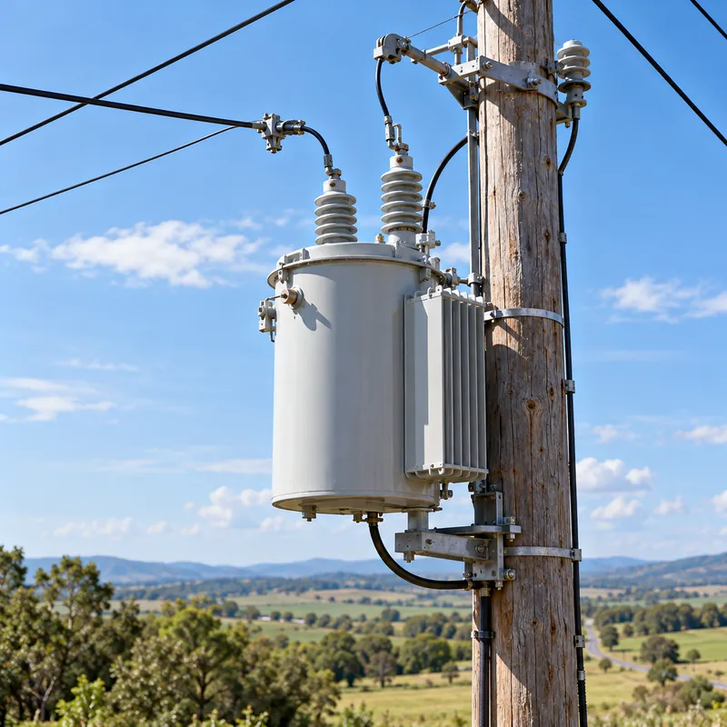
The 25 kVA single-phase transformer is one of the most familiar sights on a rural or suburban distribution line: a grey cylindrical tank on a pole, one or two primary bushings, and a triplex service drop running to nearby homes. It is a small unit, but it is the last transformation between the utility network and the customer's main panel.
This guide is for utility engineers, developers, rural electrification planners and contractors who need to understand, specify or replace a 25 kVA transformer. It covers single-phase pole-mounted designs in detail, the current values at common primary voltages, how many homes a unit can serve, fault level at the service, protection options and the data needed for an RFQ. Customer-side service work must follow local code and be done by a licensed electrician; utility-side work is for qualified line personnel only.
What Is a 25 kVA Single Phase Transformer?
A 25 kVA single-phase transformer is a distribution transformer rated to deliver 25,000 volt-amperes continuously from one primary phase to a single-phase secondary, typically 120/240 V in North America or 230 V or 240 V in IEC markets. In utility networks it is usually oil-immersed and pole-mounted; in buildings it may be a dry-type unit.
Common forms include:
- Overhead (pole-mounted), conventional: one or two primary bushings, protected externally by a fused cutout and a surge arrester. Built to IEEE C57.12.20 in North America.
- Overhead, completely self-protected (CSP): includes an internal primary weak-link fuse, a secondary thermal breaker that can signal overload, and a tank-mounted arrester.
- Single-phase pad-mounted: for underground residential distribution, with loop-feed bushings and bayonet-type fusing.
- Dry-type 480 V to 120/240 V: for indoor commercial and industrial panels.
- Three-phase 25 kVA, IEC: small 11 kV or 10 kV to 400 V units for rural villages and pumping loads.
Our general guide to the single phase pole mounted transformer covers construction and mounting; this article focuses on the 25 kVA rating specifically. For a wider view of small kVA ratings see our 30 kVA transformer guide, which concentrates on three-phase dry-type units.
25 kVA Transformer Amps: Primary and Secondary
For single-phase units, I = kVA × 1,000 / V. Primary voltage on a single-phase pole transformer is usually the line-to-neutral voltage of a multi-grounded wye distribution system.
| System (line-to-line / line-to-neutral) | Primary voltage | 25 kVA primary current |
|---|---|---|
| 4.16Y/2.4 kV | 2,400 V | 10.4 A |
| 12.47Y/7.2 kV | 7,200 V | 3.47 A |
| 13.2Y/7.62 kV | 7,620 V | 3.28 A |
| 13.8Y/7.97 kV | 7,970 V | 3.14 A |
| 24.94Y/14.4 kV | 14,400 V | 1.74 A |
| 34.5Y/19.92 kV | 19,920 V | 1.26 A |
| 11 kV (IEC, line-to-line) | 11,000 V | 2.27 A |
On the secondary, a 120/240 V split-phase winding delivers 25,000 / 240 = 104.2 A on each line at full load. Each 120 V half-winding can carry 104 A, but if all load sits on one half, that half reaches its limit at only 12.5 kVA, which is why balancing 120 V loads across both legs matters. The center-tapped secondary and its X1-X2-X3 terminals are explained in our guide to 240V single phase split-phase systems.
For a 25 kVA dry-type unit on a 480 V primary, current is 25,000 / 480 = 52.1 A, and for a three-phase 25 kVA, 400 V IEC unit, LV current is 25,000 / (1.732 × 400) = 36.1 A.
How Many Homes Can a 25 kVA Transformer Serve?
Utilities size service transformers using load diversity: homes do not reach their individual peaks at the same moment, so the combined peak is lower than the sum of individual peaks. Each utility uses its own design tables, built from metered data for its climate and customer base, so there is no universal number of homes per 25 kVA.
A worked example shows the method. Assume homes with gas heating and no EV charging, where each home's diversified peak demand, in the utility's planning data, is 5 kVA for a group of four or more homes.
- Demand for five homes:
5 × 5 kVA = 25 kVA, equal to nameplate. - Overload check: evening peaks last a few hours; IEEE C57.91 allows loading above nameplate if hot-spot temperature and ageing remain acceptable, so the utility may accept occasional peaks of, for example, 120–140% on cool evenings.
- Growth check: if two homes add 7.2 kW Level 2 EV chargers likely to run in the evening peak, demand rises toward
25 + 14.4 = 39.4 kVA, about 158% of nameplate, and the transformer should be upsized to 50 kVA.
In practice, a 25 kVA unit may serve one large all-electric home, or several smaller homes in mild climates. Heat pumps, electric heating and EV chargers have reduced diversity in many networks, pushing utilities toward 37.5 kVA and 50 kVA units for new subdivisions. Developers should always obtain the utility's own transformer assignment.
Fault Current at the Service: Why Impedance Matters
A 25 kVA transformer has low impedance compared with large units, which keeps voltage regulation good but raises fault current at the customer's service equipment. Use Isc = IFL / Z(pu) for a first estimate, assuming an infinite primary source:
| Transformer impedance | Secondary FLA at 240 V | Bolted fault at terminals (240 V) |
|---|---|---|
| 1.5% | 104.2 A | 6,950 A |
| 2.0% | 104.2 A | 5,210 A |
| 2.5% | 104.2 A | 4,170 A |
Service drop and service entrance conductor impedance reduce these values at the customer's main breaker, often substantially for long runs. Single-phase line-to-neutral (120 V) faults on a center-tapped winding can produce higher current than the 240 V line-to-line value, because the half-winding impedance is lower than half the full-winding impedance; utilities often apply a multiplier of around 1.5 for this case.
The practical consequence is that a residential main breaker with a 10 kA interrupting rating is normally adequate on a 25 kVA transformer, but larger transformers or close-coupled services can exceed it. Utilities publish maximum available fault current for their standard transformer sizes. Our fault current calculation guide shows how to include conductor impedance with the point-to-point method.
Protection: Cutouts, CSP Units and Arresters
Pole-mounted 25 kVA transformers are protected on three fronts.
- Primary overcurrent: conventional units use a fused cutout with an expulsion fuse link (K or T speed). Utilities select links from their own fusing tables, typically around two to three times primary full-load current to ride through inrush and cold-load pickup, which for a 25 kVA, 7.2 kV unit means a link in the single-digit ampere range. CSP units add an internal weak-link fuse and often still use a cutout for switching. Our transformer fuse sizing guide explains the inrush and damage-curve logic behind such tables.
- Secondary overload: CSP units include a secondary breaker with thermal elements responding to oil temperature and current; many have a signal light that warns the line crew of sustained overload before tripping.
- Surge protection: a distribution-class arrester on the primary bushing, connected with short leads to the tank ground, protects against lightning and switching surges. See our surge arrester guide for MCOV selection on multi-grounded systems.
Grounding is equally important. The transformer tank, arrester ground and secondary neutral are bonded to the system neutral and the pole ground, giving a low-impedance return for faults and surges. The wiring of primary, secondary and grounds is illustrated in our single phase pole mounted transformer wiring diagram article.
25 kVA Transformer Specifications and Physical Data
Key specification items for a 25 kVA single-phase overhead transformer:
| Parameter | Typical options |
|---|---|
| Primary voltage and BIL | 7,200 V at 95 kV BIL; 14,400 V at 125 kV BIL; 19,920 V at 125–150 kV BIL |
| Secondary voltage | 120/240 V (North America); 230 V or 240 V, or 2 × 230 V (IEC) |
| Bushings | One primary bushing (wye systems) or two (delta or phase-to-phase) |
| Taps | None, or ±2 × 2.5% off-circuit |
| Impedance | Typically about 1.5–2.5% |
| Cooling and fluid | ONAN, mineral oil or natural ester |
| Protection | Conventional or CSP |
| Mounting | Direct pole hanger brackets or crossarm |
Weight varies with design, fluid and loss level; a 25 kVA overhead unit is commonly a few hundred pounds including oil, so lifting, pole class and bracket rating must be checked against the manufacturer's outline drawing. Losses deserve attention because these units are energized 24 hours a day: in the US, DOE 10 CFR Part 431 sets minimum efficiency for liquid-immersed distribution transformers, and in other regions IEC 60076-20 or national rules apply.
For electrification programs that deploy many small units, our article on pole-mounted transformers for rural electrification covers single-wire earth return, three-phase versus single-phase choices and logistics.
Next Steps: Specifying and Sourcing
For an RFQ for 25 kVA transformers, provide:
- Quantity, kVA, phases and frequency (50 or 60 Hz).
- Primary voltage, BIL, number of bushings and tap requirements.
- Secondary voltage and configuration, e.g., 120/240 V center-tapped or 230 V.
- Standard: IEEE C57.12.00 and C57.12.20, IEC 60076, or utility specification, plus any efficiency regulation.
- Protection: conventional or CSP, arrester rating, cutout and fuse supply.
- Fluid type, paint color, mounting brackets, nameplate language and packing for export.
- Impedance range and loss evaluation figures, if the utility capitalises losses.
MARS manufactures pole-mounted transformers in single-phase and three-phase designs, along with pad-mounted transformers for underground distribution, built to IEC 60076 with ANSI/IEEE, GB and GOST variants at 50 or 60 Hz. MOQ is one unit, every transformer is routine-tested, FAT is welcome and typical lead time is 25–45 days. Send your utility specification or data sheet through the quote page.
For electrification programs or utility framework orders, agree a sample unit and type-test documentation before volume production, and specify packing that protects bushings and radiators during long sea and road transport. Ask for routine test reports per serial number, covering ratio, polarity, winding resistance, no-load and load losses, impedance and applied and induced voltage tests.
Frequently asked questions
How many amps is a 25 kVA single phase transformer?
A 25 kVA single-phase transformer delivers 104.2 A on each line of its 120/240 V secondary when the load is balanced. Each 120 V half-winding is limited to about 104 A, or 12.5 kVA. On the primary it draws 3.47 A at 7,200 V, 3.28 A at 7,620 V and 52.1 A at 480 V. Divide 25,000 VA by the voltage to find current.
How many houses can a 25 kVA transformer supply?
It depends on each utility's diversity data, climate and loads. In mild climates with gas heating, a 25 kVA unit may serve several homes; with electric heating, heat pumps or EV chargers it may serve only one or two. Utilities assign transformer size from their own design tables, so developers should request the utility's transformer assignment.
What is the fault current of a 25 kVA transformer?
With an infinite primary source, a 25 kVA, 240 V transformer with 2% impedance produces about 5.2 kA at its secondary terminals; at 1.5% impedance, about 6.9 kA. Service conductors reduce the value at the main breaker. Line-to-neutral faults on a center-tapped winding can exceed the 240 V value, so utilities often apply a multiplier.
What is a CSP transformer?
A CSP, or completely self-protected, transformer includes its own protection: an internal primary weak-link fuse, a secondary circuit breaker with thermal and overload elements, and a tank-mounted surge arrester. Many CSP units also have an overload signal light. They reduce the need for external cutouts and simplify installation on overhead distribution lines.
Can a 25 kVA transformer be overloaded?
Yes, within limits. IEEE C57.91 and IEC 60076-7 allow short-time loading above nameplate when ambient temperature is low or the overload is brief, provided winding hot-spot temperature and insulation ageing stay within acceptable values. Sustained overloads shorten life and can trip CSP secondary breakers; persistent overloading signals that a larger transformer is needed.
What size wire comes off a 25 kVA transformer?
Utilities typically use triplex aluminium service drop sized from their own standards for the 104 A full-load secondary current and voltage drop over the span. On the customer side, service entrance conductors are sized from the service rating and NEC 310 tables, not the transformer rating. A licensed electrician and the utility's service requirements govern the customer side.
Written and reviewed by the MARS application engineering team in Shanghai, who specify and test transformers, switchgear, substations and battery storage for projects in 40+ countries. Last updated .
Tags: 25 kva transformer 25 kva transformer single phase 25 kva pole mounted transformer 25 kva transformer amps 25 kva transformer 120/240