Key takeaways
- Three-phase transformer apparent power is calculated using the equation S = (V × I × √3) / 1000, where V is line-to-line voltage in volts and I is line current in amperes.
- Selecting a transformer rating requires derating the nameplate capacity for ambient temperature according to IEC 60076-2 or IEEE C57.12.00 when operating above standard 40 °C ambient baselines.
- Motor starting loads demand temporary inrush currents typically 5 to 7 times full-load amps, requiring voltage drop limits within 10% to 15% during across-the-line starting.
- Operating transformers at 50% to 70% continuous base load delivers optimal balance between capital expenditure, core loss dissipation, and winding thermal longevity.
- Harmonic currents generated by non-linear variable speed drives and power electronics require K-factor or factor-K derating to prevent winding insulation overheating.
Quick answer: A transformer sizing calculator determines the minimum rated apparent power (kVA or MVA) required to supply electrical loads safely, calculated as total apparent power divided by applicable thermal, environmental, and growth derating factors. For three-phase electrical networks, the fundamental calculation applies the equation kVA = (Volts × Amperes × 1.732) / 1000.
Properly sizing an electrical distribution or power transformer represents a critical balance between capital expenditure, energy efficiency, system reliability, and long-term operational resilience. Undersizing a transformer accelerates thermal degradation of winding insulation materials, trips medium-voltage protective devices, and invites catastrophic dielectric breakdown under sustained peak thermal stress. Conversely, severe oversizing introduces excessive capital cost, unnecessarily increases core (no-load) losses sustained 8,760 hours per year, and inflates the prospective short-circuit fault levels that downstream HV and LV switchgear must be rated to interrupt.
This engineering pillar guide outlines manual and programmatic transformer load calculations, detailing the underlying mathematical formulas, environmental derating factors defined by IEC 60076 and IEEE C57 standards, motor starting inrush constraints, and harmonic K-factor adjustments. Whether sizing an industrial unit substation or integrating commercial utility feeds, applying these precise mathematical principles ensures system compliance and lifetime asset safety.
Core Mathematical Formulas: Transformer Calculation Formula and Equations
The core transformer calculation formula converts connected active power (kW), reactive power (kVAR), or line current (A) into apparent power (kVA) to determine electrical capacity. Apparent power represents the vector sum of real power and reactive power, dictating the thermal heating experienced by transformer copper conductors and magnetic core laminations.
For single-phase installations, calculating transformer capacity follows simple linear arithmetic:
Single-Phase kVA = (Line-to-Neutral Voltage [V] × Line Current [I]) / 1,000
Rearranging this transformer formula for current yields the full-load rated current on a single-phase terminal:
Single-Phase Current (I) = (kVA × 1,000) / Line-to-Neutral Voltage [V]
For industrial and utility power systems, three phase transformer calculations introduce the square root of three (√3 ≈ 1.73205) due to the 120-degree angular phase displacement between phase conductors. The fundamental three-phase transformer calculation formulas are expressed as follows:
Three-Phase kVA = (Line-to-Line Voltage [V_LL] × Line Current [I_L] × √3) / 1,000
To compute the primary or secondary full-load rated ampacity using the standard transformer current equation, invert the expression:
Transformer Current Equation: Line Current (I_L) = (kVA × 1,000) / (Line-to-Line Voltage [V_LL] × 1.73205)
When load demand is quantified in terms of active power (kilowatts, kW) rather than line current, operating power factor (cos φ) must be accounted for:
Calculated kVA = Real Power (kW) / Power Factor (cos φ)
Consult our companion engineering article on how to size a distribution transformer for specific examples of multi-feeder commercial load aggregation.
Step-by-Step Transformer Load Calculation Methodology
Executing an accurate transformer load calculation requires a structured assessment of continuous loads, non-continuous loads, diversity factors, and future expansion headroom. Skipping disciplined load aggregation invariably leads to premature equipment replacement or nuisance overcurrent tripping.
- Compile a Connected Load Inventory: Tabulate every continuous load (operating for 3 hours or more continuously) and non-continuous load connected downstream of the transformer. Group loads by category: general resistive heating, linear lighting, variable frequency drive (VFD) loads, and direct-on-line (DOL) electric motors.
- Convert Active Power to Apparent Power: Convert all kilowatt (kW) ratings into kVA by dividing the active power by the operational power factor of each individual circuit:
kVA = kW / PF. Typical default values are 0.80 for standard industrial induction motors, 0.90 for modern industrial facilities with power factor correction, and 0.95 to 1.0 for resistive heating circuits. - Apply Demand and Diversity Factors: Rarely do all installed branch loads operate simultaneously at peak draw. Apply an operational demand factor (the ratio of maximum demand to total connected load) and a diversity factor across separate load groups in accordance with local electrical codes (e.g., IEC 60364 or NEC Article 220). Demand factors typically range from 0.70 to 0.85 in mixed industrial manufacturing environments.
- Sum Base Apparent Power (kVA_base): Aggregate the coincident peak apparent power values:
kVA_coincident = Σ (kVA_individual × Demand Factor). - Factor Future Load Growth: Incorporate a realistic facility expansion headroom margin, typically 20% to 25%, to prevent premature transformer replacement when subsequent plant lines or tenant spaces are added:
kVA_growth = kVA_coincident × 1.25. - Select Nearest Standard Rating: Round the calculated minimum kVA up to the nearest standard commercial transformer rating defined by regional manufacturing frameworks (such as 315, 400, 500, 630, 800, 1000, 1250, 1600, 2000, or 2500 kVA).
For broader network topology planning involving integrated secondary distribution networks, consult our comprehensive three-phase transformer buyer's guide.
Standard kVA Ratings and Transformer Sizing Guide Lookup Table
Using a standardized transformer sizing guide allows electrical engineers to quickly reference full-load ampacities across low-voltage and medium-voltage interfaces. Standardizing on globally manufactured capacity ratings guarantees availability of replacement units, standard switchgear busbar matchings, and compliant protection curves.
The table below provides full-load secondary currents calculated across typical global standard three-phase transformer nameplate ratings at standard operating voltages (400 V European/IEC and 480 V North American/ANSI), alongside medium-voltage primary currents at 11 kV:
| Nominal Transformer Rating (kVA) | Full Load Amps at 400 V, 3-Phase (A) | Full Load Amps at 480 V, 3-Phase (A) | Full Load Amps at 11,000 V, 3-Phase (A) | Typical Impedance (%Z at rated kVA) |
|---|---|---|---|---|
| 100 | 144.3 | 120.3 | 5.25 | 4.00% |
| 160 | 230.9 | 192.5 | 8.40 | 4.00% |
| 250 | 360.8 | 300.7 | 13.12 | 4.00% |
| 315 | 454.7 | 378.9 | 16.53 | 4.00% |
| 400 | 577.4 | 481.1 | 20.99 | 4.00% |
| 500 | 721.7 | 601.4 | 26.24 | 4.00% - 5.00% |
| 630 | 909.4 | 757.9 | 33.07 | 4.00% - 5.00% |
| 800 | 1,154.7 | 962.3 | 41.99 | 5.00% - 6.00% |
| 1,000 | 1,443.4 | 1,202.8 | 52.49 | 5.00% - 6.00% |
| 1,250 | 1,804.2 | 1,503.5 | 65.61 | 5.00% - 6.00% |
| 1,600 | 2,309.4 | 1,924.5 | 83.98 | 6.00% - 7.00% |
| 2,000 | 2,886.8 | 2,405.6 | 104.97 | 6.00% - 7.00% |
| 2,500 | 3,608.4 | 3,007.0 | 131.22 | 7.00% |
| 3,150 | 4,546.6 | 3,788.9 | 165.33 | 7.00% - 8.00% |
When engineering complete packaged substations, the transformer's full load current dictates primary switch-disconnector selections and secondary main circuit breaker trip settings inside prefabricated transformer substations.
Accounting for Electric Motor Inrush and Peak Starting Surges
To correctly size a transformer serving inductive machinery, the engineer must account for transient motor starting currents that exceed standard running currents by hundreds of percent. Squirrel-cage induction motors drawn directly online (DOL) generate instantaneous starting currents between 500% and 700% of their rated full-load amperes (FLA).
During direct-on-line motor energisation, the transformer's internal leakage impedance (%Z) produces an instantaneous internal voltage drop. If transformer capacity is inadequate, secondary terminal voltage can sag below the 85% to 90% threshold required to hold electromagnetic contactors closed, potentially resetting sensitive automated programmable logic controllers (PLCs) or causing motor stalling due to reduced starting torque (torque is proportional to voltage squared):
Voltage Drop (%) ≈ (kVA_starting / kVA_transformer) × %Z × sin(θ)
To evaluate if your transformer size calculator calculation satisfies motor inrush without excessive sag, apply this proven engineering rule of thumb:
- Direct-on-Line (DOL) Starting: The dedicated transformer kVA must generally be at least 2.5 to 3.0 times the running kVA of the largest individual induction motor starting across the line, plus 100% of the running capacity of all concurrently running loads.
- Star-Delta (Y-Δ) Starters: Inrush current reduces to approximately 33% of DOL levels, lowering the required starting headroom multiplier to roughly 1.5 times motor running kVA.
- Soft Starters: Starting current is limited electronically to 250% to 350% of FLA, allowing a reduced sizing margin.
- Variable Frequency Drives (VFDs): Inrush current is restricted to 100% to 120% of rated FLA; however, VFD rectifiers introduce severe harmonic currents that necessitate winding thermal derating instead.
Environmental Derating Factors: Temperature, Elevation, and Harmonics
A raw transformer load calculation must be adjusted downward if site environmental conditions exceed the reference baselines established by IEC 60076-1 (maximum 40 °C ambient, 30 °C monthly average, 20 °C annual average) or IEEE C57.12.00 standards. Failure to apply environmental derating factors results in insulation temperatures exceeding the maximum thermal limit (e.g., 105 °C for Class A oil-immersed paper systems, or 180 °C to 220 °C for Class H dry-type windings), drastically cutting asset operating life.
When sizing transformer equipment for hostile field conditions, evaluate the following three site criteria:
- Ambient Temperature Derating: For every degree Celsius that the continuous ambient air temperature exceeds standard baseline ratings (typically 40 °C daily peak), reduce the usable output capacity of an oil-immersed transformer by roughly 1% to 1.5%, or by 1% for dry-type units, unless a higher winding temperature rise was explicitly specified to the factory.
- High Altitude / Thin Air Derating: Transformers installed at elevations exceeding 1,000 metres (3,300 feet) above sea level experience degraded convective cooling due to lower atmospheric air density, alongside decreased dielectric breakdown strength of external air clearances. Apply a continuous thermal derating factor of approximately 0.4% per 100 metres above the 1,000-metre threshold for oil-natural air-natural (ONAN) liquid-immersed transformers, and up to 0.5% per 100 metres for forced air ventilated dry-type units.
- Harmonic Current Derating (K-Factor): Non-linear power electronic loads such as computing servers, uninterruptible power supplies (UPS), and rectifier bridges induce harmonic frequencies (e.g., 3rd, 5th, 7th, 11th orders). High-frequency harmonic currents dramatically elevate eddy current losses and stray load losses in copper windings. For high-harmonic loads, specify an ANSI K-factor transformer (e.g., K-4, K-13, or K-20) or derate standard distribution units using the IEC 61378 or IEEE C57.110 factor-K calculations.
Deciding between cooling configurations under harsh field conditions is covered thoroughly in our comparative analysis of oil-immersed vs dry-type transformers.
Economic Sizing: Loading Ratios and Total Cost of Ownership
Optimal engineering sizing rarely means selecting a transformer that runs at exactly 95% to 100% of continuous rated capacity under typical daily operations. Transformers achieve their maximum operating thermodynamic and electrical efficiency when core losses (no-load losses) equal load losses (winding copper losses), which typically happens between 40% and 65% of rated nameplate loading.
Total Cost of Ownership (TCO) calculations integrate initial capital expenditure against the cumulative cost of active electrical losses over a 25- to 35-year design life:
TCO = Purchase Price + (A × No-Load Loss [kW]) + (B × Load Loss [kW])
Where coefficients 'A' and 'B' reflect regional capitalised monetary values per kilowatt of waste heat loss over time. A unit running perpetually at 95% load incurs parabolic (I²R) copper loss dissipation, leading to high operating thermal strain and rapid coolant breakdown. Conversely, purchasing a massive 2,000 kVA transformer to feed a steady 300 kVA continuous load imposes high upfront capital costs and continuous core magnetisation iron losses that never scale down with low power consumption.
For deep mathematical evaluations on capitalised loss formulas, read our detailed technical paper on transformer losses and total cost of ownership.
Common Engineering Pitfalls in Transformer Sizing
Even experienced consulting engineers encounter errors when converting preliminary load schedules into finalised transformer procurement specifications. Avoiding frequent computational mistakes ensures project capital efficiency and eliminates site commissioning bottlenecks.
- Confusing Real Power (kW) with Apparent Power (kVA): Sizing a transformer by treating total connected kilowatts as required kVA ignores lagging power factors. A 1,000 kW plant load operating at an uncorrected 0.80 power factor draws 1,250 kVA; attempting to serve this on a 1,000 kVA transformer subjects the unit to a continuous 25% thermal overload.
- Neglecting Neutral Return Currents from Triplen Harmonics: Single-phase non-linear loads (such as modern LED drivers and switched-mode power supplies) generate zero-sequence triplen harmonics (3rd, 9th, 15th) that do not cancel in the neutral conductor of a three-phase wye system. Instead, they add up arithmetically in the neutral terminal, necessitating a 200% rated neutral busbar and delta-wye vector configuration.
- Ignoring Downstream Fault Level Implications: Specifying an oversized transformer with low percentage impedance (%Z) drastically increases prospective secondary symmetrical short-circuit current (I_sc = I_rated / %Z). This forces electrical engineers to specify substantially more expensive, higher kA-rated breakers across every downstream panelboard.
- Omitting Transformer Self-Consumption in Renewable Schemes: In utility-scale solar photovoltaic plants and battery energy storage integration, step-up transformers remain connected to the transmission grid overnight. Core magnetisation losses during non-generating hours represent parasitic energy consumption that must be incorporated into lifetime financial yield calculations.
Next steps: specifying and sourcing
Determining the final engineering rating for your facility requires balancing precise load schedules, motor starting parameters, environmental deratings, and total ownership economics. Once you complete your base transformer sizing calculator assessments, compile your full operational specifications—including primary and secondary voltages, BIL ratings, vector group, impedance range, and site ambient extremes.
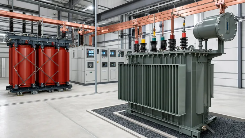
Our dedicated manufacturing engineering team is available to validate your capacity calculations and provide custom factory design drawings across our extensive lines of standard and bespoke oil-immersed distribution transformers and high-efficiency dry-type cast resin transformers. Contact our application engineering desk directly or submit your detailed project load schedule via our formal transformer quotation request page to receive a full technical proposal within 24 hours.
Frequently asked questions
How do you calculate kVA for a 3-phase transformer?
Calculate three-phase kVA by multiplying line-to-line voltage in volts by line current in amperes, multiplying by the square root of three (1.732), and dividing the result by 1,000. Alternatively, divide total connected load in kilowatts by the operational power factor.
What size transformer do I need for a 500 kW load?
A 500 kW load operating at a standard 0.85 power factor requires an apparent power capacity of 588 kVA. Factoring in a recommended 20% future growth and reliability margin (706 kVA), the correct commercial size to select is an 800 kVA standard rated transformer.
What is the formula for transformer full load current?
The formula for full load current in a three-phase transformer is I = (kVA × 1,000) / (Line-to-Line Voltage × 1.732). For a single-phase transformer, the formula is I = (kVA × 1,000) / Line-to-Neutral Voltage.
How does power factor affect transformer sizing?
A lower power factor increases the total apparent power (kVA) required to deliver the same real work (kW), necessitating a physically larger transformer. If the power factor drops from 1.0 to 0.70, the transformer kVA capacity must increase by roughly 43% to deliver identical active power.
What is the ideal continuous loading percentage for a distribution transformer?
The ideal continuous loading percentage for maximum electrical efficiency and operational longevity is between 50% and 70% of nameplate rating. Running continuously near 100% accelerates insulation aging, while operating below 30% results in poor capital utilisation and disproportionate core loss costs.
How do you size a transformer for motor starting?
Size the transformer so that the transient voltage drop during motor starting remains within 10% to 15%. For standard direct-on-line motors with inrush currents 6 times rated full-load amps, the transformer capacity in kVA should typically be at least 2.5 to 3 times the motor running kilowatt rating.
Tags: transformer sizing calculator transformer calculation formula calculating transformer kva transformer load calculation three phase transformer calculations


