Key takeaways
- Power factor equals kW divided by kVA; a 400 kW load at 0.75 PF draws 533 kVA, while at 0.95 PF it draws only 421 kVA.
- Displacement power factor is cos φ; true power factor also includes harmonic distortion, PF = cos φ / √(1 + THD²) for sinusoidal voltage.
- Capacitor correction required is Q_c = P × (tan φ₁ − tan φ₂), so raising 400 kW from 0.75 to 0.95 PF needs about 221 kvar.
- Conductor and transformer copper losses scale with current squared, so correcting 0.75 to 0.95 PF cuts those losses by about 37%.
- Induction motor power factor falls sharply at light load, which is why oversized, lightly loaded motors are a leading cause of poor site PF.
Quick answer: Power factor is the ratio of real power to apparent power in an AC circuit, PF = P / S = kW / kVA. It ranges from 0 to 1 and has no units. For sinusoidal circuits it equals cos φ, the cosine of the angle between voltage and current. A low power factor means more current, larger transformers and higher losses for the same useful work.
Power factor shows up on utility bills as a penalty line, on transformer specifications as a sizing assumption and on motor nameplates as a two-digit number few people read. It describes how effectively a load converts the current it draws into useful work, and it has direct consequences for equipment size, losses, voltage drop and energy cost.
This guide is for facility engineers, energy managers and designers. It gives the power factor definition used in electrical engineering, the formulas and power triangle, methods to calculate, measure and figure power factor from bills and meters, why motors and electronic loads behave the way they do, and how to size correction with worked examples.
What Is Power Factor in Electrical Systems?
Power factor is the ratio of real power, which does work, to apparent power, which the supply must deliver. Its definition in electrical engineering is PF = P / S, where P is in watts and S in volt-amperes. Because both are powers, power factor units are none: it is a dimensionless number between 0 and 1, often written as a percentage.
The meaning is practical. A circuit at 1.0 PF uses all the current it draws to deliver energy. A circuit at 0.7 PF draws about 43% more current than it would need at unity for the same kilowatts. That extra current produces no useful output, yet it heats cables, loads transformers and causes voltage drop.
Leading and lagging
- Lagging PF: current lags voltage; caused by inductive loads such as motors, transformers and reactors.
- Leading PF: current leads voltage; caused by capacitive loads such as capacitor banks, long lightly loaded cables and some electronic power supplies.
- Unity PF: current in phase with voltage; resistive heaters, incandescent lamps.
Power factor in an AC circuit arises because inductors and capacitors store energy and return it to the source every half-cycle. That oscillating exchange is reactive power, measured in var. It averages to zero energy, but the current carrying it is real and must be supplied. The detailed formulas for P, Q and S, including three-phase versions, are covered in apparent, reactive and real power; this article focuses on power factor itself and how to improve it.
Power Factor Formula and the Power Triangle
The power triangle is a right triangle with real power P on the horizontal side, reactive power Q on the vertical side and apparent power S as the hypotenuse. The power factor angle φ lies between P and S.
PF = cos φ = P / SS = √(P² + Q²)tan φ = Q / P, soQ = P × tan φφ = arccos(PF)
| Power factor | Angle φ | tan φ (kvar per kW) | kVA per kW | Current vs unity PF |
|---|---|---|---|---|
| 1.00 | 0° | 0.000 | 1.000 | 100% |
| 0.95 | 18.2° | 0.329 | 1.053 | 105% |
| 0.90 | 25.8° | 0.484 | 1.111 | 111% |
| 0.85 | 31.8° | 0.620 | 1.176 | 118% |
| 0.80 | 36.9° | 0.750 | 1.250 | 125% |
| 0.75 | 41.4° | 0.882 | 1.333 | 133% |
| 0.70 | 45.6° | 1.020 | 1.429 | 143% |
| 0.60 | 53.1° | 1.333 | 1.667 | 167% |
The electrical power triangle makes one point obvious: improving PF from 0.95 to 1.0 gains little, while improving 0.7 to 0.9 releases a large share of capacity. Most correction schemes target 0.95 to 0.98 because the last few points cost far more capacitance for very little benefit.
The same triangle applies per phase or in total for three-phase systems. For the relationship between kVA ratings and kW output, see kVA vs kW.
How to Calculate Power Factor
There are several ways of working out power factor, depending on the data available.
From measured power, voltage and current
Single phase: PF = P / (V × I). Three phase: PF = P / (√3 × V_L × I_L).
Example: a 480 V three-phase feeder carries 120 A and a meter reads 82 kW. S = 1.732 × 480 × 120 = 99.8 kVA; PF = 82 / 99.8 = 0.82 lagging.
From utility energy data
Average power factor over a billing period: PF = kWh / √(kWh² + kvarh²).
Example: a month with 120,000 kWh and 90,000 kvarh gives PF = 120,000 / √(120,000² + 90,000²) = 120,000 / 150,000 = 0.80. Many tariffs apply a penalty or a kVA-based demand charge below a threshold set by the utility; the threshold and method vary by tariff and country, so check the actual contract.
From impedance
PF = R / Z = R / √(R² + X²). A load of 8 Ω resistance and 6 Ω inductive reactance has Z = 10 Ω and PF = 0.8.
From nameplate data
Motor nameplates often state PF or allow it to be derived: PF = P_out / (√3 × V × I × η). A 75 kW, 400 V motor at 135 A and 95% efficiency: 75,000 / (1.732 × 400 × 135 × 0.95) = 0.84.
Always state whether the figure is instantaneous, average, displacement or true PF, since they can differ substantially.
Motor Power Factor and Other Common Loads
The power factor of an electric motor comes from its magnetizing current. An induction motor needs a roughly constant magnetizing current to establish flux in the air gap regardless of load, plus a load current that does work. At full load the work component dominates and PF is typically in the 0.8–0.9 range for medium motors. At light load the magnetizing component dominates and PF falls steeply, often well below 0.5 at no load.
This explains why plants with many oversized, lightly loaded motors have poor PF even though each motor is rated reasonably. Right-sizing motors, or running them through variable frequency drives whose rectifier front end presents a high displacement PF to the supply, can improve site PF before any capacitors are added. More motor characteristics are in the three-phase electric motor guide.
| Load type | Typical displacement PF | Notes |
|---|---|---|
| Resistive heating | 1.0 | No correction needed |
| Induction motor, full load | 0.80–0.90 | Larger and higher-speed motors higher |
| Induction motor, light load | 0.3–0.6 | Magnetizing current dominates |
| VFD with diode front end | 0.95 or higher | True PF lower due to harmonics |
| Transformer at no load | Low | Magnetizing current only, small in kVA |
| Arc furnaces, welders | 0.6–0.8 | Fluctuating; dynamic compensation used |
| LED drivers with PFC | 0.9 or higher | Depends on driver quality |
Values are indicative; actual figures depend on design and loading and should be measured. Transformers themselves contribute magnetizing and leakage reactive power, a share that rises with load.
Displacement vs True Power Factor: The Effect of Harmonics
Cos φ describes the phase shift of the fundamental current, called displacement power factor. Nonlinear loads such as rectifiers, drives, UPS systems and electronic ballasts also draw harmonic currents. These increase RMS current without contributing real power at the fundamental, reducing true power factor.
With sinusoidal voltage, PF_true = PF_disp × 1 / √(1 + THD_i²), where THD_i is total harmonic current distortion as a fraction.
Worked example
A drive-fed load has displacement PF 0.97 and current THD of 40%. PF_true = 0.97 / √(1 + 0.16) = 0.97 / 1.077 = 0.90. A capacitor bank cannot fix the 0.07 shortfall caused by harmonics; it only corrects displacement.
Worse, capacitors and the supply transformer's leakage inductance form a parallel resonant circuit. The resonant harmonic order is approximately h_r ≈ √(S_sc / Q_c), where S_sc is the short-circuit power at the bus. With a 1,000 kVA transformer at 6% impedance, S_sc is about 16.7 MVA; adding 400 kvar gives h_r ≈ √(16,700 / 400) ≈ 6.5, uncomfortably close to the 5th and 7th harmonics of six-pulse drives. Detuned capacitor banks with series reactors, commonly tuned near 3.8–4.2 times fundamental (7% or 5.67% reactor), or active filters are the usual remedy.
Do not confuse this with the insulation power factor test (tan δ) on transformers and bushings, which measures dielectric losses in insulation, explained in the power factor test guide.
Power Factor Correction: Sizing Capacitors with a Worked Example
Capacitors supply reactive power locally, so the supply no longer carries it. The capacitance power factor relationship gives required compensation:
Q_c = P × (tan φ₁ − tan φ₂)
Worked example: 400 kW at 480 V, 0.75 to 0.95
tan φ₁ = tan(arccos 0.75) = 0.882tan φ₂ = tan(arccos 0.95) = 0.329Q_c = 400 × (0.882 − 0.329) = 221 kvar; select a 225 kvar automatic bank in steps.- kVA before:
400 / 0.75 = 533 kVA; after:400 / 0.95 = 421 kVA; released capacity 112 kVA. - Current before:
533,000 / (1.732 × 480) = 641 A; after:421,000 / (1.732 × 480) = 507 A. - I²R loss ratio:
(507 / 641)² = 0.63, a 37% reduction in conductor and transformer copper losses upstream of the bank.
Where to install correction
- At individual motors: best loss reduction, but capacitors must not exceed motor magnetizing kvar to avoid self-excitation after disconnection.
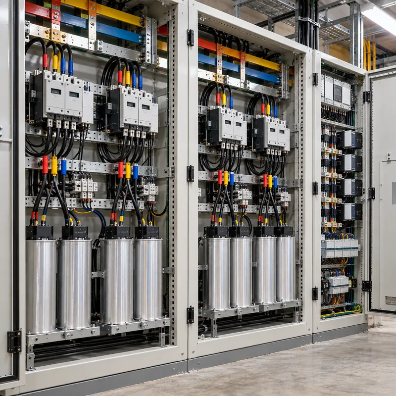
- At the main LV switchboard: automatic stepped bank controlled by a PF relay; the common choice.
- At MV: for large plants with MV motors or tariff metering at MV.
Capacitors are rated per IEC 60831 for LV self-healing types and IEC 60871 for MV. Released transformer capacity can defer an upgrade; whether a 1,000 kVA unit is still adequate after load growth is a sizing exercise covered in the transformer kVA sizing guide.
How to Measure Power Factor
Measuring power factor accurately requires simultaneous voltage and current sampling. Options, in increasing capability:
- Panel power meters on switchboard feeders read PF, kW, kvar and kVA continuously; class 0.5S or better for energy accounting.
- Clamp-on power meters for spot checks of single loads.
- Power-quality analyzers record displacement PF, true PF and harmonics over days, essential before designing correction.
- Utility revenue meters provide interval kWh and kvarh, the basis for tariff calculations.
Good practice is to log at least one representative production week, capturing minimum and maximum kvar demand so the bank's step size and total can be chosen. Record PF on each major feeder as well as the main incomer, because correction at the main bus does nothing to reduce losses in downstream cables. Measurements on energized equipment must follow NFPA 70E with suitably rated instruments.
The relationship between VA and W on equipment nameplates is explained in volt-ampere vs watts.
Next Steps: Specifying and Sourcing
Power factor affects transformer and switchboard specifications in three ways: kVA sizing, the LV switchboard layout for a compensation section, and harmonic design of the transformer itself. In an RFQ, include:
- Measured or estimated kW demand and existing PF, and the target PF after correction.
- Harmonic spectrum or THD of the load, needed for transformer eddy-loss design and detuned bank selection.
- Whether the LV switchboard should include space and busbar provisions for a reactive compensation section.
- Transformer impedance, so resonance with planned capacitor kvar can be checked.
- Loss evaluation values, since reduced current from correction affects total cost of ownership.
MARS supplies oil-immersed distribution transformers and IEC 61439 low-voltage switchboards for industrial and commercial sites, designed to the stated load and harmonic profile. Send load and PF data via the quotation page for a matched proposal.
Frequently asked questions
What is power factor in simple terms?
Power factor is the share of the current drawn by equipment that actually does useful work. It equals real power in kilowatts divided by apparent power in kilovolt-amperes. A power factor of 1 means all current is useful; 0.8 means the supply carries 25% more current than the work requires.
What is the formula for power factor?
PF = P / S, real power divided by apparent power. For sinusoidal waveforms PF = cos φ, where φ is the phase angle between voltage and current. In three-phase systems, PF = P / (√3 × V_L × I_L). With harmonics present, true PF = displacement PF divided by √(1 + THD²).
How do you find power factor from kW and kVA?
Divide kW by kVA. A transformer delivering 680 kW while loaded to 800 kVA operates at 680 / 800 = 0.85 power factor. Both values must be measured at the same time and point; using a demand kW from one period and kVA from another gives misleading results.
What is a good power factor?
Most industrial sites aim for 0.95 or higher, which avoids typical utility penalties and frees capacity in transformers and cables. Raising PF above about 0.98 yields little benefit and risks a leading power factor at light load. The exact threshold for penalties depends on the local tariff.
What are the units of power factor?
Power factor has no units. It is the ratio of two powers, watts and volt-amperes, so the units cancel. It is written as a decimal between 0 and 1, such as 0.92, or as a percentage, with the qualifier lagging or leading to show whether current trails or leads voltage.
Why is motor power factor low at light load?
An induction motor needs nearly constant magnetizing current to create its magnetic field. At light load the working current is small, so the reactive magnetizing current dominates and the power factor drops, often below 0.5 at no load. Correctly sized motors running near rated load have much better power factor.
Does improving power factor save energy?
It reduces current, so I²R losses in cables and transformers upstream of the correction fall, and it can lower kVA demand charges. It does not reduce the kilowatts the load itself consumes. Savings depend on tariff structure, cable lengths and where correction is installed.
Written and reviewed by the MARS application engineering team in Shanghai, who specify and test transformers, switchgear, substations and battery storage for projects in 40+ countries. Last updated .
Tags: power factor power factor formula how to calculate power factor power factor triangle motor power factor