Key takeaways
- NEC Table 250.122 sizes the equipment grounding conductor from the overcurrent device rating: 60 A needs 10 AWG copper and 200 A needs 6 AWG copper.
- Grounding electrode conductors use Table 250.66, based on the largest service conductor; 3/0 copper service conductors need a 4 AWG copper GEC.
- When phase conductors are upsized for voltage drop, NEC 250.122(B) requires the EGC to increase in the same circular-mil proportion.
- Parallel feeders need a full-size EGC in every raceway per 250.122(F); a 1,600 A feeder in four conduits needs 4/0 copper in each.
- System bonding jumpers above 1,100 kcmil copper equivalent are sized at 12.5% of the largest phase conductor area under Table 250.102(C)(1).
Quick answer: An equipment grounding conductor chart is NEC Table 250.122, which sizes the EGC from the rating of the overcurrent device protecting the circuit, not from conductor ampacity. For example, a 100 A breaker needs 8 AWG copper, 200 A needs 6 AWG, 400 A needs 3 AWG and 800 A needs 1/0. Grounding electrode conductors are sized separately from Table 250.66.
Grounding conductors are sized by different rules from the circuit conductors they run with, and by different rules from each other. An equipment grounding conductor depends on the breaker or fuse ahead of it; a grounding electrode conductor depends on the size of the service or transformer secondary conductors; bonding jumpers follow yet another table. Mixing up the tables is a common plan-review finding.
This guide is for electrical designers, contractors and substation engineers working to the NEC. It sets out the equipment grounding conductor table and the grounding electrode conductor table, explains upsizing, parallel runs and motor circuits, and works through a complete transformer example. Service and building wiring must be installed by a licensed electrician under the locally adopted code edition, which should always be checked for amendments.
Equipment Ground vs Grounding Electrode Conductor: Which Is Which?
Four conductors are often loosely called the ground wire. Each has a distinct job and sizing rule.
- An equipment grounding conductor (EGC) is the conductor that connects non-current-carrying metal parts of equipment to the system grounded conductor at the source, providing the low-impedance fault path that trips the overcurrent device.
- A grounding electrode conductor (GEC) connects the system grounded conductor or equipment to the grounding electrode system: rods, building steel, concrete-encased electrodes or a ground ring.
- A grounded conductor is the system conductor intentionally connected to earth, usually the neutral. It carries load current.
- A bonding jumper (main, system or supply-side) connects the grounded conductor and the EGC at the service or separately derived system, or bonds enclosures on the line side of overcurrent protection.
| Conductor | NEC sizing rule | Sized from | Carries current |
|---|---|---|---|
| Equipment grounding conductor | Table 250.122 | Overcurrent device rating | Fault current only |
| Grounding electrode conductor | Table 250.66 | Largest service or SDS conductor | Lightning, surges, earth faults |
| Main / system bonding jumper | Table 250.102(C)(1) | Largest ungrounded conductor | Fault current |
| Grounded (neutral) conductor | Load per Art. 220; minimum per 250.24(C) | Load and minimum table | Load and fault current |
The EGC must form an effective ground-fault current path under NEC 250.4(A)(5): low enough impedance to let enough fault current flow to operate the protective device quickly. Its size is therefore tied to that device, which is why the equipment grounding conductor table is indexed by amperes of protection rather than by load.
NEC Table 250.122: Equipment Grounding Conductor Chart
The chart reproduces NEC Table 250.122 minimum sizes for copper and aluminum or copper-clad aluminum EGCs. Use the rating or setting of the automatic overcurrent device in the circuit ahead of the equipment, conduit or raceway.
| Overcurrent device rating (A), not exceeding | Copper | Aluminum or copper-clad Al |
|---|---|---|
| 15 | 14 AWG | 12 AWG |
| 20 | 12 AWG | 10 AWG |
| 60 | 10 AWG | 8 AWG |
| 100 | 8 AWG | 6 AWG |
| 200 | 6 AWG | 4 AWG |
| 300 | 4 AWG | 2 AWG |
| 400 | 3 AWG | 1 AWG |
| 500 | 2 AWG | 1/0 |
| 600 | 1 AWG | 2/0 |
| 800 | 1/0 | 3/0 |
| 1,000 | 2/0 | 4/0 |
| 1,200 | 3/0 | 250 kcmil |
| 1,600 | 4/0 | 350 kcmil |
| 2,000 | 250 kcmil | 400 kcmil |
| 2,500 | 350 kcmil | 600 kcmil |
| 3,000 | 400 kcmil | 600 kcmil |
| 4,000 | 500 kcmil | 750 kcmil |
| 5,000 | 700 kcmil | 1,200 kcmil |
| 6,000 | 800 kcmil | 1,200 kcmil |
Read the next row up when a rating falls between values: a 90 A breaker uses the 100 A row, 8 AWG copper. The table gives minimums; the EGC may need to be larger to meet 250.4(A)(5), for example on very long circuits where fault current would otherwise be too low to trip the breaker quickly. Under 250.122(A), the EGC is not required to be larger than the circuit conductors supplying the equipment.
Metal raceways such as rigid conduit and EMT can also serve as the EGC under 250.118, though many designers add a wire-type EGC.
How to Size an Equipment Grounding Conductor
The equipment grounding conductor sizing procedure is short, but each step has a rule behind it.
- Identify the overcurrent device protecting the circuit: its rating for fuses and fixed breakers, or its trip setting for adjustable breakers.
- Read Table 250.122 for copper or aluminum.
- Check whether phase conductors were upsized beyond the minimum for ampacity; if so, increase the EGC proportionally per 250.122(B).
- Count raceways or cables in parallel; each gets a full-size EGC per 250.122(F).
- Apply special rules for motor circuits (250.122(D)) or flexible cords.
- Confirm the EGC need not exceed the size of the circuit conductors.
Worked example: what size ground for 3/0 feeders?
A 200 A, 480 V three-phase feeder uses 3/0 copper conductors (200 A at 75°C) on a 200 A breaker. Table 250.122, 200 A row: 6 AWG copper EGC, or 4 AWG aluminum.
The same 3/0 conductors used as service-entrance conductors raise a different question: the grounding electrode conductor, from Table 250.66, is 4 AWG copper (2/0 or 3/0 copper row). Asking what size ground for 3/0 feeders therefore has two correct answers depending on which ground is meant.
Ampacity of the circuit conductors themselves is set by NEC Table 310.16 and derating; that process, and how the grounding conductor fits into the full calculation, is explained in the wire size calculator guide.
Upsizing for Voltage Drop, Parallel Runs and Motor Circuits
Voltage drop: NEC 250.122(B)
If ungrounded conductors are increased above the minimum size needed for ampacity, the EGC must be increased by the same ratio of circular mil area. The logic is that a longer circuit has higher fault-loop impedance, so the EGC needs the same proportional improvement.
Example: the 200 A feeder above is upsized from 3/0 (167,800 cmil) to 250 kcmil (250,000 cmil) for a long run. Ratio 250,000 / 167,800 = 1.49. Minimum EGC area: 26,240 × 1.49 = 39,100 cmil, so the 6 AWG becomes 4 AWG copper (41,740 cmil).
Parallel conductors: NEC 250.122(F)
Where conductors are run in parallel in multiple raceways or cables, an EGC sized from the full overcurrent device rating is required in each raceway or cable. A 1,600 A feeder in four conduits, each with three 600 kcmil phases, needs a 4/0 copper EGC in every conduit, not one quarter of it. Where parallel conductors share one raceway, a single EGC suffices.
Motor circuits: NEC 250.122(D)
For motor branch circuits protected by an instantaneous-trip breaker or motor short-circuit protector, the EGC may be sized from the rating of the motor overload device rather than the higher short-circuit device setting, but not smaller than Table 250.122 based on that overload rating.
| Situation | Rule | Effect on EGC |
|---|---|---|
| Phases upsized for voltage drop | 250.122(B) | Increase by cmil ratio |
| Parallel raceways | 250.122(F) | Full size in each raceway |
| Multiple circuits in one raceway | 250.122(C) | One EGC sized for largest OCPD |
| Motor circuits with instantaneous trip | 250.122(D) | May be based on overload rating |
| Feeder taps | 250.122(G) | Based on the feeder OCPD ahead of the tap |
Grounding Electrode Conductor Size Chart (NEC Table 250.66)
The grounding electrode conductor table is indexed by the size of the largest ungrounded service-entrance conductor, or the equivalent area for parallel sets. For a separately derived system, use the largest ungrounded secondary conductor.
| Largest service conductor, copper | Largest service conductor, aluminum | GEC copper | GEC aluminum |
|---|---|---|---|
| 2 AWG or smaller | 1/0 or smaller | 8 AWG | 6 AWG |
| 1 or 1/0 | 2/0 or 3/0 | 6 AWG | 4 AWG |
| 2/0 or 3/0 | 4/0 or 250 kcmil | 4 AWG | 2 AWG |
| Over 3/0 to 350 kcmil | Over 250 to 500 kcmil | 2 AWG | 1/0 |
| Over 350 to 600 kcmil | Over 500 to 900 kcmil | 1/0 | 3/0 |
| Over 600 to 1,100 kcmil | Over 900 to 1,750 kcmil | 2/0 | 4/0 |
| Over 1,100 kcmil | Over 1,750 kcmil | 3/0 | 250 kcmil |
The table tops out at 3/0 copper. A GEC does not carry utility fault current, which returns over the grounded conductor; it stabilizes voltage to earth and carries surge currents.
Electrode-specific limits: NEC 250.66(A)–(C)
- Sole connection to rod, pipe or plate electrodes: not required to be larger than 6 AWG copper or 4 AWG aluminum.
- Sole connection to a concrete-encased electrode: not required to be larger than 4 AWG copper.
- Sole connection to a ground ring: not required to be larger than the ring conductor.
So a 200 A dwelling service with 2/0 copper conductors needs a 4 AWG copper GEC to building steel or a water pipe electrode, but only 6 AWG to the rods. For transformer grounding practice beyond the NEC minimum, see the transformer grounding system guide.
Transformer Ground Size: Worked Separately Derived System Example
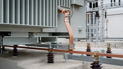
A transformer secondary is a separately derived system under NEC 250.30, so it needs its own system bonding jumper, grounding electrode conductor and EGCs. Example: 500 kVA, 480 V delta to 208Y/120 V dry-type or oil-filled transformer in a building.
- Secondary current:
500,000 / (1.732 × 208) = 1,388 A. Secondary conductors: four parallel sets of 600 kcmil copper (4 × 420 A = 1,680 A) to a 1,600 A main breaker. - Equivalent area:
4 × 600 = 2,400 kcmilcopper. - Grounding electrode conductor: over 1,100 kcmil row of Table 250.66: 3/0 copper.
- System bonding jumper: Table 250.102(C)(1), over 1,100 kcmil: 12.5% of 2,400 kcmil = 300 kcmil copper.
- Secondary EGCs: 1,600 A breaker, Table 250.122: 4/0 copper in each of the four raceways.
- Primary side:
500,000 / (1.732 × 480) = 601 A. Primary-only protection at up to 125% per Table 450.3(B) gives 751 A, rounded to an 800 A device under its notes. Primary EGC from Table 250.122: 1/0 copper.
A supply-side bonding jumper run with the secondary conductors, if the bond is made at the first disconnect instead of the transformer, is sized the same way as the system bonding jumper. Make the bond at one point only; a second bond would place neutral current on the EGCs, one cause of the problems described in neutral to ground voltage.
Overcurrent device selection for both windings is covered in the transformer breaker size chart.
Grounding in Substations and Medium Voltage Systems
Above 1,000 V, NEC Article 250 Part X applies, and EGCs for MV feeders are sized from Table 250.122 using the fuse rating or relay overcurrent setting. In practice, substation earthing is governed by a fault-current and touch-voltage design rather than a table.
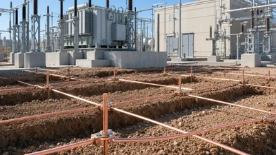
- Grounding grid design. IEEE 80 calculates grid resistance, ground potential rise and permissible touch and step voltages from fault current, clearing time and soil resistivity. Grid conductor size is found from the fault current and duration, commonly 4/0 copper or larger, or 95–120 mm² in IEC practice. See the substation grounding grid design guide.
- Conductor thermal check. Any grounding conductor expected to carry high fault current for longer than a typical breaker clearing time should be checked with the adiabatic relation
A = I × √t / k, or the IEEE 80 conductor sizing equation. - Neutral grounding. Resistance-grounded systems limit fault current, which reduces conductor duty; the resistor and its conductors are rated for the let-through current and time, as described in the neutral earthing resistor guide.
- Switchgear and transformer bonding. MV switchgear earth bars, transformer tanks, LV neutral and cable screens all bond to the grid, each with conductors rated for the relevant fault.
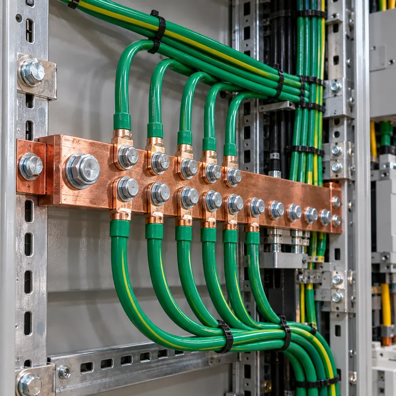
Compact and containerized substations combine MV switchgear, transformer and LV switchboard in one enclosure, so a single earth bar arrangement, with clearly labelled connections for HV earth, LV neutral and enclosure, simplifies site bonding. Switchboard ground buses sized per IEC 61439 or UL 891 then connect the outgoing feeder EGCs; see the LV switchboard engineering guide.
Next Steps: Specifying and Sourcing
Grounding details are easier to get right when the equipment arrives ready for them. In an RFQ for a transformer, substation or switchboard, state:
- System grounding: solidly grounded wye, resistance grounded or ungrounded, on both MV and LV sides.
- Where the system bonding jumper is to be made: at the transformer or at the first disconnect.
- Ground bus rating and lug provisions for the GEC, EGCs and parallel feeder grounds, with conductor sizes from your calculations.
- Neutral bushing and bus rating relative to phase current.
- Available fault current and clearing time for grounding conductor and grid thermal checks.
- Standard: NEC and UL/IEEE for North America, or IEC 60076, IEC 62271 and IEC 61439 elsewhere.
MARS supplies compact and containerized transformer substations and MV and LV switchgear with earth bars and terminations arranged to the customer's grounding design. Send your single-line diagram and grounding requirements through the quotation page.
Frequently asked questions
What size ground wire do I need for a 200 amp feeder?
For a feeder protected by a 200 A overcurrent device, NEC Table 250.122 requires a minimum 6 AWG copper or 4 AWG aluminum equipment grounding conductor. If the phase conductors are upsized for voltage drop, the EGC must be increased by the same circular-mil ratio.
What size ground for 3/0 feeders?
It depends on the overcurrent device, not the 3/0 conductors. On a 200 A breaker, the equipment grounding conductor is 6 AWG copper. If the 3/0 copper conductors are service-entrance conductors, the grounding electrode conductor from Table 250.66 is 4 AWG copper, or 6 AWG if connected only to rods.
How is the grounding electrode conductor sized?
Use NEC Table 250.66 based on the largest ungrounded service-entrance or separately derived system conductor, or the equivalent area of parallel sets. Sizes range from 8 AWG to 3/0 copper. Connections only to rod electrodes need not exceed 6 AWG copper, and to concrete-encased electrodes 4 AWG copper.
What is the difference between an equipment grounding conductor and a grounding electrode conductor?
The equipment grounding conductor bonds equipment enclosures back to the source and carries fault current to trip the breaker; it is sized from Table 250.122. The grounding electrode conductor connects the system to earth electrodes and is sized from Table 250.66 based on service conductor size.
Does each parallel conduit need its own ground wire?
Yes. NEC 250.122(F) requires an equipment grounding conductor in each raceway or cable of a parallel set, each sized from the full rating of the overcurrent device. A 1,200 A feeder in four conduits needs a 3/0 copper EGC in every conduit.
Can the equipment grounding conductor be smaller than Table 250.122?
No, the table gives minimum sizes. The only reduction is that the EGC need not be larger than the circuit conductors, and motor circuits with instantaneous-trip protection may base the EGC on the overload rating. Longer circuits may need a larger EGC to ensure the breaker trips quickly.
Written and reviewed by the MARS application engineering team in Shanghai, who specify and test transformers, switchgear, substations and battery storage for projects in 40+ countries. Last updated .
Tags: equipment grounding conductor chart grounding electrode conductor equipment grounding conductor size nec grounding chart transformer ground size chart