Key takeaways
- Neutral to ground voltage equals neutral current times neutral conductor impedance, so 16 A on 100 ft of 12 AWG copper gives about 3.2 V.
- NEC 250.24 and 250.30 require the neutral to be bonded to ground at one point, the service or the separately derived transformer.
- In a balanced linear three-phase wye system the neutral carries almost zero current, but triplen harmonics add and can exceed phase current.
- Three-phase delta systems have no neutral unless a center tap or grounding transformer creates one; wye systems provide a 4-wire neutral.
- A reading near zero under heavy load at a remote outlet suggests an illegal downstream neutral-ground bond that puts current on protective conductors.
Quick answer: Neutral to ground voltage is the voltage measured between the grounded neutral conductor and the equipment ground at a point of use. It is near zero at the transformer or service bond and rises downstream as load current flows through neutral resistance. A few volts under load is normal; high or fluctuating readings indicate overload, harmonics, loose connections or improper neutral-ground bonding.
Few measurements cause as much confusion on site as a voltmeter reading between neutral and ground. The neutral is grounded, so many people expect zero; instead they see 1 V, 4 V or sometimes much more, and the reading changes as loads switch. Sensitive electronics may lock up, data networks may show errors, and the question becomes whether the installation is safe and compliant.
This guide is for facility engineers, electricians and power-quality specialists. It explains where neutral voltage comes from, how three-phase neutral current behaves, what the bonding rules require at the transformer and service, and a structured way to diagnose high readings. Work on energized service equipment must follow local code and be carried out by a licensed electrician using appropriate PPE.
What Is Neutral to Ground Voltage?
The neutral, or grounded conductor, is the current-carrying return conductor connected to the star point of a wye transformer or the center tap of a split-phase winding. The equipment grounding conductor is a separate, normally non-current-carrying conductor that bonds metal enclosures together and returns fault current. The two are joined at exactly one location: the main bonding jumper at the service, or the system bonding jumper at a separately derived system such as a transformer.
At that bonding point the voltage between neutral and ground is effectively zero. Downstream, the neutral carries the return current of single-phase loads while the grounding conductor carries none. The neutral's resistance therefore produces a voltage drop that the grounding conductor does not, and the difference is measured as voltage between neutral and ground:
V_NG ≈ I_N × Z_N
where I_N is the neutral current and Z_N the impedance of the neutral path from the bonding point to the measurement point, including every splice and terminal.
So does a neutral wire have voltage? Relative to ground at the bonding point, it should have almost none; relative to ground at the far end of a loaded circuit, it does, and that small voltage is a normal consequence of Ohm's law. The rules for sizing the grounding conductor that sits alongside it are covered in the equipment grounding conductor sizing guide.
What Causes Voltage on a Neutral Wire?
Neutral voltage has a short list of causes. Most real installations show a combination.
- Load current through neutral resistance. The normal, unavoidable component. Long branch circuits and small conductors increase it.
- Triplen harmonics. Electronic power supplies, LED drivers and drives draw third-harmonic current that adds in a shared neutral instead of cancelling.
- Loose or corroded connections. A high-resistance neutral splice raises V_NG and, in severe cases, shifts the neutral so that phase-to-neutral voltages become unequal.
- Shared or borrowed neutrals. A neutral used by circuits on the same phase, rather than different phases, carries the sum of their currents.
- Improper bonding. A neutral-ground bond in a subpanel puts neutral current on the grounding conductor and on conduit, causing circulating currents and magnetic fields.
- Utility neutral voltage. On multi-grounded distribution systems, primary neutral current flowing through the earth and the bonding network can raise the local neutral relative to remote earth, sometimes noticed in agricultural facilities as stray voltage.
- Open neutral. The dangerous case: loads on different legs end up in series across line-to-line voltage, so some see overvoltage and some undervoltage.
Only the first cause is benign. The others signal overload, poor workmanship or a code violation, and should be traced. In transformer-fed systems, a neutral that is undersized for harmonic loads is a design issue, discussed further below.
Does 3 Phase Have a Neutral?
It depends on how the source winding is connected. A wye (star) secondary has a natural star point that can be brought out as a neutral, giving a four-wire system with two voltages, for example 208Y/120 V, 480Y/277 V or 400/230 V. A delta secondary has no star point, so a three-wire delta system supplies only line-to-line voltage unless a winding is center-tapped, as in a 240/120 V high-leg delta, or a grounding transformer creates a neutral.
| System | Neutral available | Line-to-neutral voltage | Typical use |
|---|---|---|---|
| 208Y/120 V wye | Yes | 120 V on all phases | Commercial buildings |
| 480Y/277 V wye | Yes | 277 V on all phases | Industrial, lighting |
| 400/230 V wye | Yes | 230 V on all phases | IEC markets |
| 240/120 V high-leg delta | Yes, center tap | 120 V on A and C; 208 V on B | Older light industrial |
| 480 V delta | No | None | Motors, process loads |
| Corner-grounded delta | Grounded phase, not a neutral | None | Legacy installations |
A three phase with neutral system is what most distribution transformers deliver, typically Dyn11 or Dyn1, as described in the 3 phase 4 wire system guide. The high-leg arrangement, where one phase reads 208 V to neutral, is explained in high-leg delta transformers.
Three-Phase Neutral Wire Current and Harmonics
In a balanced three-phase four-wire system with linear loads, the three phase currents are equal and 120° apart, so their phasor sum in the neutral is zero. With unbalanced linear loads, the neutral carries only the imbalance. This is why the neutral wire in 3 phase systems has traditionally been allowed to match, not exceed, the phase conductors.
Nonlinear loads change that. Third, ninth and fifteenth harmonics (triplens) are in phase with each other on all three phases, so they add arithmetically in the neutral: I_N,3 = 3 × I_3,phase.
Worked example: office floor on 208Y/120 V
Each phase carries 30 A fundamental and a third-harmonic component of 33% of fundamental, about 10 A. The fundamentals cancel in the neutral; the third harmonics add: I_N = 3 × 10 = 30 A at 180 Hz. The RMS phase current is √(30² + 10²) = 31.6 A, so the neutral carries 95% of phase current even with perfectly balanced loading. With higher harmonic content the neutral can exceed phase current.
Consequences for the neutral to ground voltage are direct: 30 A at 180 Hz flowing through a feeder neutral produces a voltage drop that appears at every outlet downstream. Under NEC 310.15(E), the neutral of a 4-wire wye circuit is counted as a current-carrying conductor when the major portion of the load is nonlinear. Design responses include a double-size neutral, K-rated or harmonic-mitigating transformers, and dedicated neutrals per circuit. Delta primaries on the supplying transformer trap triplen currents so they do not propagate to the MV network, which is one reason Dyn vector groups dominate, as covered in star and delta connections.
What Is a Normal Voltage Between Neutral and Ground?
The NEC does not set a numerical limit for neutral-to-ground voltage. Its requirements concern conductor sizing, a single neutral-ground bond, and the informational recommendation that branch-circuit voltage drop not exceed about 3% and combined feeder and branch drop about 5%. Many equipment manufacturers and power-quality practitioners use around 2 V at the receptacle as a practical target for sensitive electronics, and treat readings above roughly 5 V under normal load as worth investigating.
Worked example: branch circuit drop
A 120 V circuit runs 100 ft of 12 AWG copper to a load drawing 16 A. NEC Chapter 9 Table 8 gives about 1.98 Ω per 1,000 ft for stranded uncoated 12 AWG copper. Neutral resistance: 100 × 1.98 / 1,000 = 0.198 Ω. Neutral voltage: 16 × 0.198 ≈ 3.2 V. The hot conductor drops the same 3.2 V, so the load sees about 120 − 6.4 = 113.6 V, a 5.3% drop. The N-G reading is a symptom of a long, heavily loaded circuit, not a fault.
| Reading at outlet | Load condition | Likely meaning |
|---|---|---|
| Below 0.5 V | Heavy load | Possible illegal N-G bond nearby; check panel |
| 0.5–2 V | Normal load | Typical for short, adequately sized circuits |
| 2–5 V | Normal load | Long run, high load or harmonics; check sizing |
| Above 5 V | Any | Overload, loose neutral, shared neutral or harmonics |
| Present with no load | Circuit off | Induced voltage, shared neutral or upstream issue |
| Fluctuating widely | Varying loads | Failing neutral connection; urgent |
How to Troubleshoot High Neutral to Ground Voltage
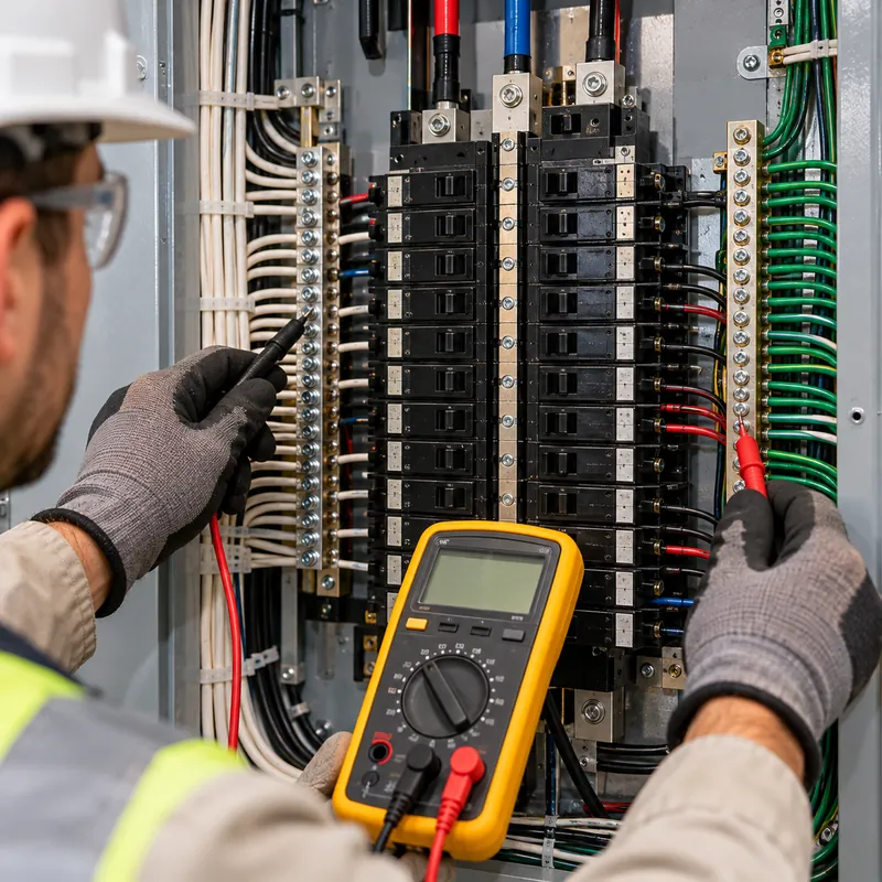
A methodical approach separates normal drop from defects. Measurements on live equipment must be made by qualified persons following NFPA 70E, with a meter rated for the measurement category of the location.
- Measure at the load and at the panel. Record V_NG at the outlet and at the panel neutral and ground bars. If the panel reads near zero and the outlet reads high, the cause lies in the branch circuit.
- Measure neutral current. Use a true-RMS clamp meter on the neutral and each phase. Compare neutral current with the expected imbalance; a large excess suggests harmonics or a shared neutral.
- Remove the load. If V_NG collapses with the load off, the reading was I × R drop. If it persists, look upstream or for induced voltage on long parallel runs.
- Check harmonic content. A power-quality analyzer shows third-harmonic current on the neutral. High values point to a neutral sizing or transformer selection issue.
- Inspect connections. With the circuit isolated, check torque and condition of neutral terminals, splices and bars; infrared scanning under load helps locate hot joints.
- Verify single-point bonding. Confirm the only neutral-ground bond is at the service or transformer. Clamp the grounding conductor: any steady current indicates a downstream bond or a neutral-to-ground fault.
- Correct and re-measure. Shorten or upsize circuits, separate shared neutrals, fix bonds or add harmonic mitigation, then repeat the measurements under load.
Where a separately derived transformer close to the load is added, it re-establishes a fresh neutral-ground bond and resets V_NG near zero for the loads it supplies. Grounding at transformers is detailed in the transformer grounding system guide.
Neutral Bonding at the Transformer and 3 Phase Power Cable Selection
Under NEC 250.30, a separately derived system such as a delta-wye transformer secondary must have a system bonding jumper connecting the neutral to the grounding conductors at one point, either at the transformer or at the first disconnect, not both. A grounding electrode conductor connects that point to the building electrode system. Doing it twice creates a parallel path that carries neutral current on enclosures and conduit.
For pad-mounted transformers supplying a building, the bond is usually made at the service equipment, while the transformer neutral (X0) is also bonded to the transformer tank and grounding electrode under utility rules for multi-grounded systems. The details of grounding electrodes and grids are in the substation grounding grid design guide.
Choosing a 3 phase power cable
- 3 conductors + ground: three-wire delta or balanced three-phase loads such as motors.
- 4 conductors + ground: four-wire wye with single-phase loads; neutral full size, or oversized where harmonics are high.
- Insulated ground: separate isolated grounding conductor for sensitive equipment, still bonded at the same single point.
Conductor colors also differ between systems; see 3 phase power color codes. Where MV systems use resistance earthing to limit fault current, the neutral earthing resistor sits between the transformer neutral and ground, covered in the neutral earthing resistor guide.
Next Steps: Specifying and Sourcing
If neutral voltage problems trace back to the supply transformer, or a new building needs a clean four-wire supply, specify the transformer with neutral performance in mind:
- Vector group with a brought-out, fully rated secondary neutral, for example Dyn11 400/230 V or Dyn1 480Y/277 V.
- Neutral bushing rating relative to phase current; ask for 100% or 200% neutral where harmonic loads dominate.
- Expected harmonic spectrum or K-factor of the load, so the winding eddy-current losses can be designed for.
- Grounding arrangement: neutral bonded inside the transformer, or isolated for bonding at the service, and grounding pad provisions.
- Primary voltage, kVA, impedance, loop or radial feed for pad-mounted units.
MARS supplies pad-mounted transformers and oil-immersed distribution transformers with grounded wye secondaries to IEEE C57.12.00 and IEC 60076, routine tested before shipment. Send load details and grounding requirements through the quotation page.
Frequently asked questions
Should there be voltage between neutral and ground?
At the service or transformer bonding point, essentially none. At a loaded outlet, a small voltage is normal because neutral current flows through conductor resistance while the grounding conductor carries no current. One to two volts is typical on short circuits; several volts on long, heavily loaded or harmonic-rich circuits warrants investigation.
Do neutral wires have voltage?
A neutral wire carries current and has a small voltage relative to ground along its length, proportional to that current and its resistance. If the neutral is disconnected upstream while a load remains connected, the neutral on the load side can rise to full line voltage, so it must always be treated as potentially live.
Does 3 phase have a neutral?
Only wye-connected and center-tapped delta systems provide a neutral. A 208Y/120, 480Y/277 or 400/230 V system has a neutral from the transformer star point. A plain 480 V or 600 V delta system has three phase conductors and a grounding conductor but no neutral.
Why is there current on my three phase neutral if the load is balanced?
Balanced linear currents cancel in the neutral, but triplen harmonics from electronic loads add. If each phase carries 10 A of third harmonic, the neutral carries 30 A at 180 Hz on 60 Hz systems. True-RMS clamp measurements and a harmonic analyzer confirm this.
What does high neutral to ground voltage mean?
It usually means excessive neutral current, a long or undersized circuit, harmonic loading, a shared neutral, or a loose neutral connection. A wildly fluctuating reading suggests a failing neutral joint, which can lead to an open neutral and damaging overvoltage on connected equipment.
Can I bond neutral and ground in a subpanel?
No. Under NEC 250.24(A)(5) and 250.142(B), neutral and grounding conductors must not be connected on the load side of the service disconnect, except at a separately derived system such as a transformer. Downstream bonds put neutral current on enclosures and grounding conductors.
Written and reviewed by the MARS application engineering team in Shanghai, who specify and test transformers, switchgear, substations and battery storage for projects in 40+ countries. Last updated .
Tags: neutral to ground voltage voltage between neutral and ground does a neutral wire have voltage 3 phase neutral three phase neutral wire