Key takeaways
- In a star connection V_line = √3 × V_phase and I_line = I_phase, so a 400 V star system puts 231 V across each winding.
- In a delta connection V_line = V_phase and I_line = √3 × I_phase, which is why delta windings carry 58% of line current.
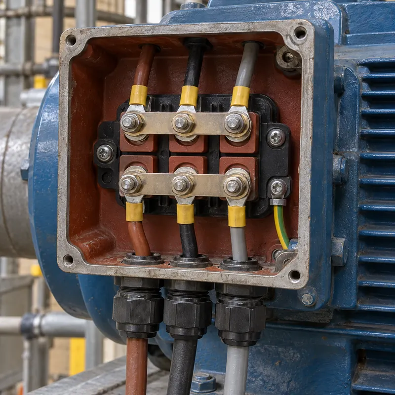
- An IEC motor terminal box uses U1-V1-W1 and W2-U2-V2; two horizontal links joining W2, U2 and V2 make star; three vertical links make delta.
- Starting a delta-run motor in star cuts winding voltage to 58% and reduces both starting line current and torque to one third.
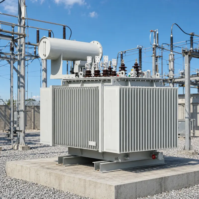
- Distribution transformers are commonly Dyn11 per IEC 60076-1: delta HV traps triplen harmonics while the star LV provides a loadable neutral.
Quick answer: A star and delta connection are the two ways to join three windings. In star (wye), one end of each winding meets at a neutral point, so line voltage is √3 times phase voltage and line current equals phase current. In delta, windings form a closed loop, so line voltage equals phase voltage and line current is √3 times phase current. Total power is identical.
Every three-phase machine, from a 5 kW pump motor to a 31.5 MVA power transformer, has its windings joined either in star or in delta. That single choice decides the voltage each winding must insulate, the current each conductor carries, whether a neutral is available and how harmonics and earth faults behave.
This guide is written for electrical engineers, panel builders and maintenance technicians who need the relationships, the terminal wiring and the design reasons in one place. It covers motors first, because that is where most wiring questions arise, then transformers, where the connection becomes part of the vector group on the nameplate.
What Is a Star Connection and What Is a Delta Connection?
A star connection (also called wye or Y) joins one end of each of the three windings at a common point, the star point or neutral, and feeds the free ends from lines L1, L2 and L3. A delta connection (Δ) joins the end of each winding to the start of the next, forming a closed triangle, with a line connected at each corner.
In star, each winding sits between a line and the neutral, so it sees the phase voltage. The phasor difference between two phase voltages 120° apart is √3 times larger, which gives the line-to-line voltage. In delta, each winding sits directly between two lines, so it sees full line voltage, while each line conductor carries the phasor difference of two winding currents.
Core relationships
- Star:
V_L = √3 × V_ph,I_L = I_ph - Delta:
V_L = V_ph,I_L = √3 × I_ph - Both:
P = √3 × V_L × I_L × PF
Because the power equation uses line quantities, a balanced load draws the same kilowatts whichever way it is connected, as long as each winding receives its rated voltage. What changes is the voltage stress per winding and the current per winding. The conversion between equivalent star and delta impedances, used in network calculations, is covered in our delta to wye conversion guide.
Star vs Delta Connection: What Is the Difference?
The table compares the two connections as they are used in motors, transformers and loads. The values assume a balanced 400 V, 50 Hz system; for 480 V, 60 Hz systems the star phase voltage is 277 V.
| Property | Star (wye) | Delta |
|---|---|---|
| Voltage across each winding | V_L / √3 (231 V on 400 V) | V_L (400 V) |
| Current in each winding | Equal to line current | Line current / √3 |
| Neutral point | Available, can be earthed | None (unless a corner or mid-tap is grounded) |
| Insulation per winding | Lower, suits HV windings | Full line voltage |
| Conductor size per winding | Larger cross-section | Smaller cross-section, more turns |
| Triplen harmonics | Flow in neutral if earthed | Circulate inside the loop |
| Typical use | LV distribution, HV windings, motor start | Motor run, transformer primaries, tertiaries |
A practical rule follows from the table. Star suits high voltage and low current, because each winding sees only 58% of line voltage; that is why many HV transformer windings are star connected and graded towards the neutral. Delta suits high current at lower voltage and gives a path for third-harmonic magnetizing current, which keeps the flux and the output voltage waveform sinusoidal.
Neither is universally better. The choice depends on whether a neutral is needed, how the system is earthed and what voltage the equipment insulation is rated for.
How Do You Wire a Motor Connection in Star or Delta?
Most IEC motors bring six winding ends to the terminal box, marked per IEC 60034-8: U1, V1, W1 on the top row and W2, U2, V2 on the bottom row. The offset order on the bottom row is deliberate, so that short brass links can make either connection without crossing.
| Connection | Links fitted | Supply to | Typical nameplate |
|---|---|---|---|
| Star (Y) | W2–U2–V2 joined by two horizontal links | U1, V1, W1 | Y 690 V (on Δ400/Y690 motor) |
| Delta (Δ) | U1–W2, V1–U2, W1–V2 by three vertical links | U1, V1, W1 | Δ 400 V |
Reading the nameplate is the first step. A motor marked Δ400/Y690 V must be connected in delta on a 400 V supply; connected in star on 400 V it would run with only 231 V per winding, develop one third of its torque and overheat under load. A motor marked Δ230/Y400 V must be star connected on 400 V; delta on 400 V would overvoltage each winding by 73% and saturate the iron.
Procedure for wiring star or delta
- Isolate, lock out and prove dead per NFPA 70E or local equivalent.
- Read rated voltage and connection from the nameplate.
- Fit links for star (bottom row) or delta (vertical pairs) as required.
- Connect L1, L2, L3 to U1, V1, W1 and the protective conductor to the earth stud.
- Torque terminals to the manufacturer's value and close the box with its gasket.
- Bump the motor to check direction; swap any two lines to reverse it.
Electric Motor Delta Connection: Why Run in Delta and Start in Star?
A delta wired motor rated for the supply voltage can be started in star to reduce inrush. In star each winding sees V_L / √3, so winding current falls to 58%, and because line current in star equals winding current while in delta it is √3 times winding current, line current drops to one third. Torque, proportional to voltage squared, also drops to one third.
Worked example: 11 kW, Δ400 V motor
Full-load current: I = P / (√3 × V × η × PF) = 11,000 / (1.732 × 400 × 0.90 × 0.85) ≈ 20.8 A. In delta, each winding carries 20.8 / 1.732 ≈ 12.0 A.
If locked-rotor current direct-on-line is 7 × FLC, about 146 A, then star starting draws roughly 146 / 3 ≈ 49 A. If the motor delivers 260% of rated torque at locked rotor in delta, it offers only about 87% in star, so the driven load must need less than that during acceleration. Fans and centrifugal pumps usually qualify; loaded conveyors and positive-displacement compressors often do not.
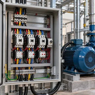
The transition from star to delta is open or closed. Open transition briefly disconnects the motor and can create a current and torque spike larger than the original inrush; closed transition uses resistors to bridge the gap. Timer settings, contactor sizing (main and delta contactors at 58% of FLC, star contactor at 33%) and overload placement are explained in the star-delta starter guide. For the coil geometry inside the stator, see the coil arrangement in a delta-connected motor.
Star-Star and Delta-Delta Motor Connection on Dual-Voltage Motors
NEMA-style dual-voltage motors often have nine leads numbered 1 to 9. Each phase is split into two half-windings that are placed in series for the higher voltage and in parallel for the lower voltage. The terms star star motor connection (parallel wye, YY) and delta delta motor connection (parallel delta, ΔΔ) refer to the low-voltage arrangements.
Nine-lead wye-connected motor (230/460 V)
- High voltage (series wye): L1–1, L2–2, L3–3; join 4–7, 5–8, 6–9.
- Low voltage (parallel wye): L1–1 and 7, L2–2 and 8, L3–3 and 9; join 4–5–6 as a second star point.
Nine-lead delta-connected motor (230/460 V)
- High voltage (series delta): L1–1, L2–2, L3–3; join 4–7, 5–8, 6–9.
- Low voltage (parallel delta): L1–1, 6, 7; L2–2, 4, 8; L3–3, 5, 9.
Twelve-lead motors expose all ends and can be connected series or parallel in either star or delta, which allows star-delta starting at both voltages and part-winding starting. Always follow the connection diagram on the motor plate, since lead numbering can differ between manufacturers and older machines. More diagrams for common motor configurations are collected in the 3 phase motor wiring diagrams article.
A common field fault on a dual-voltage motor is a single half-winding reversed. The motor will run, but with unbalanced currents, noise and heating; a winding resistance comparison and a phase current check at no load usually reveal it.
Star and Delta Connection in Transformers
In transformers the connection of each winding is coded in the vector group. Capital letters describe the HV winding (D, Y, Z), lower case the LV winding (d, y, z), N or n indicates a brought-out neutral, and the clock number gives the phase displacement in 30° steps. The full system is explained in transformer vector groups explained.
| Vector group | Typical application | Why chosen |
|---|---|---|
| Dyn11 / Dyn1 | MV/LV distribution, 10–35 kV to 400/230 V or 480Y/277 V | LV neutral fully loadable, delta absorbs triplens, isolates zero sequence |
| YNd11 / YNd1 | Generator step-up, grid step-down | Star HV allows graded insulation and solid earthing |
| YNyn0 + d tertiary | Transmission autotransformers, large Y-Y units | Delta tertiary stabilizes neutral and supplies auxiliaries |
| Yzn11 | Small rural units with unbalanced load | Zigzag LV handles unbalance with low zero-sequence impedance |
| Dd0 | Industrial isolation, three-phase-only loads | No neutral, survives one unit out as open delta in banks |
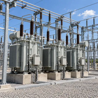
A star delta star connection usually means a star-star transformer with a third, delta-connected winding. A pure star-star transformer with an isolated primary neutral cannot supply single-phase load from the secondary neutral without the neutral voltage shifting, and its magnetizing current lacks a third-harmonic path. Adding a delta tertiary, as described in the three-winding transformer guide, provides that path and limits neutral shift.
Delta Star Wiring: Practical Checks Before Energizing
Delta star wiring errors are easy to make and costly to find late. Whether the equipment is a motor, a transformer bank built from single-phase units or a load bank, the following checks are worth doing before energization.
- Polarity of each winding. One reversed winding in a delta produces a circulating current of roughly twice phase voltage divided by the loop impedance; on a transformer bank this trips protection or damages windings. Measure the open corner voltage before closing the delta: it should be near zero.
- Neutral and earthing. On a star secondary, bond the neutral to earth at one point only, normally at the transformer or the service. Multiple bonds put load current on the protective conductors, a cause of neutral to ground voltage problems downstream.
- Phase displacement. If a new Dyn11 transformer will run in parallel with an existing unit, the vector group and phase sequence must match exactly.
- Ratio and voltage. Measure line-to-line and line-to-neutral voltage on the star side. On a 400/230 V system the ratio between them should be √3.
Winding resistance and turns-ratio tests at the factory confirm the internal connection; every MARS oil-immersed and dry-type transformer is routine tested to IEC 60076-1, including vector group verification, and FAT witnessing is welcome. Site tests then confirm external links, phasing and neutral bonding.
Next Steps: Specifying and Sourcing
When a transformer or motor-supply project reaches the RFQ stage, state the connection requirements explicitly rather than leaving them to assumption.
- Rated voltages on both sides and the required vector group (for example 11 kV Dyn11 400/230 V or 13.8 kV Dyn1 480Y/277 V).
- Whether the LV neutral will be fully loaded, and its required current rating relative to phase current.
- System earthing on both sides: solidly earthed, resistance earthed or isolated.
- Parallel operation with existing units, with their vector group, impedance and tap range.
- Large motor loads, their starting method and expected voltage dip on the transformer.
- Frequency (50 or 60 Hz) and the design standard: IEC 60076, IEEE C57.12.00 or GB.
MARS supplies oil-immersed distribution and power transformers and cast-resin dry-type transformers in any standard vector group, with typical lead times of 25–45 days for distribution units. Send your single-line diagram and load list through the quotation request page and our engineers will confirm the winding connections, neutral rating and test plan.
Frequently asked questions
What is the difference between star and delta connection?
In star, the three windings share a common neutral point, each winding sees line voltage divided by 1.732 and carries full line current. In delta, the windings form a closed loop, each sees full line voltage and carries line current divided by 1.732. Star provides a neutral; delta does not but traps third-harmonic currents.
Is a motor more powerful in star or delta?
A motor produces its rated power only in the connection that applies rated voltage to each winding. A Δ400/Y690 V motor on 400 V must run in delta; in star it develops about one third of the torque. Star is used on such motors only during starting to cut inrush current.
How do I know if my motor is wired in star or delta?
Open the terminal box with the motor isolated. Two horizontal links joining W2, U2 and V2 indicate star. Three vertical links joining U1-W2, V1-U2 and W1-V2 indicate delta. Compare with the nameplate voltage marking to confirm the connection matches the supply.
What happens if a star motor is connected in delta?
If a motor designed for star on the supply voltage is connected in delta, each winding receives 1.73 times its rated voltage. The iron saturates, magnetizing current rises sharply and the windings overheat within minutes; protection should trip, but insulation damage is likely if it does not.
Why do distribution transformers use delta-star (Dyn11)?
The delta primary gives triplen harmonic currents a circulating path and blocks zero-sequence current from the MV network, while the star secondary provides a neutral for single-phase 230 V or 277 V loads and a solid earthing point. Dyn11 is the most common group for IEC distribution transformers.
Can a three-phase system without neutral be star connected?
Yes. A three-wire star connection is common for balanced loads such as motors and heaters, where the star point is not connected to a supply neutral. The phase voltages stay balanced only while the load is balanced; single-phase loads need a four-wire star system with a solidly connected neutral.
Written and reviewed by the MARS application engineering team in Shanghai, who specify and test transformers, switchgear, substations and battery storage for projects in 40+ countries. Last updated .
Tags: star and delta connection star delta connection star vs delta connection delta connection for motor star delta star connection