Key takeaways
- Transformer wire must be sized to carry 125% of the transformer rated full-load current continuously under standard terminal conditions per NEC Article 450.3 and IEC 60364-5-52.
- Internal magnet wire must comply with thermal class ratings up to Class 220 (Class C) under IEC 60076-11, whereas external connection cables require insulation rated for the maximum ambient operating temperature and terminal lug heat rise.
- Short-circuit thermal withstand sizing requires calculating the conductor cross-section using the adiabatic equation from IEC 60909 or IEEE 242 based on system symmetrical fault current.
- Copper conductors offer 38% higher conductivity than aluminium by volume, reducing winding window fill factor and busbar terminal footprint in tight enclosure enclosures.
- External cable terminations require strict adherence to minimum bend radius standards (typically 8 to 12 times cable diameter) to prevent mechanical stress on transformer bushings.
Quick answer: Transformer wire refers both to the internal electromagnetic magnet wire wound around the core and the external supply and load power cables connecting the terminals. Sizing requires calculating continuous load ampacity with a minimum 125% safety factor, verifying short-circuit thermal withstand duration, and matching insulation thermal classes to IEC 60076 or IEEE C57 standards.
Selecting the correct conductor cross-section and insulation profile is a critical design phase for any power distribution installation. Whether specifying rectangular magnet wire for medium-voltage coil fabrication or engineering external feeder runs, undersized conductors cause severe overheating, dielectric degradation, and premature transformer failure. External cabling must handle heavy cyclical loading, system fault dynamics, and elevated terminal box temperatures without exceeding operational limits.
This engineering guide covers conductor metallurgy, insulation thermal classes, step-by-step sizing calculations for both primary and secondary circuits, and essential terminal connection practices. For foundational wiring layouts and phase vector verification, refer to our detailed transformer wiring schematic guide.
Magnet Wire vs External Cable for Transformer Terminals
An electrical engineer must distinguish between the internal winding wire and the external cable for transformer connection. Internal transformer wire—traditionally termed magnet wire—consists of solid copper or aluminium conductors coated with micro-thin dielectric enamels (such as polyesterimide overcoated with polyamide-imide) or wrapped in Nomex, aramid paper, or Kraft paper. Its primary function is to pack the maximum number of turns into the core window area while sustaining continuous operating temperatures from 105°C (Class A) up to 220°C (Class C or H) per IEC 60076-11.
Conversely, external terminal cabling connects the transformer primary bushings and secondary low-voltage terminals to switchgear, distribution boards, or industrial loads. These cables utilise standard Class 2 stranded or Class 5 flexible conductors insulated with cross-linked polyethylene (XLPE), ethylene propylene rubber (EPR), or polyvinyl chloride (PVC). External cables operate under external installation standards, such as IEC 60364-5-52 and NFPA 70 (National Electrical Code Article 310), where ratings rarely exceed 90°C conductor operating temperatures.
Physical transitions at the transformer bushings demand strict thermal separation. Heat generated inside an enclosed tank or ventilated dry enclosure radiates directly onto terminal palms. If external cabling with standard 70°C PVC insulation is bolted directly to a low-voltage bushing running at 90°C to 105°C, thermal migration degrades the cable sheath, leading to phase-to-phase flashovers. For detailed step-by-step bushing connection procedures, consult our technical guide on how to hook up a transformer.
Conductor Metallurgy: Copper vs Aluminium Selection
Selecting between copper and aluminium transformer wire depends on spatial boundaries, total equipment mass, dynamic mechanical stress, and procurement budgets. Electrolytic Tough Pitch (ETP) copper (CW004A / C11000) provides an electrical conductivity of 100% IACS (International Annealed Copper Standard), equating to a volume resistivity of 0.01724 Ω·mm²/m at 20°C. Electrical-grade aluminium alloy (EC 1350) yields approximately 61% IACS conductivity with a resistivity of 0.02826 Ω·mm²/m.
Because aluminium requires roughly 1.6 times the cross-sectional area of copper to carry identical continuous current, aluminium-wound units demand a larger core cross-section and expanded tank dimensions. However, aluminium weighs roughly half as much as copper for an equivalent current rating. In structural or rooftop installations where floor loading is constrained, aluminium conductors offer distinct structural advantages despite the expanded geometric footprint.
When selecting external power cabling, copper remains the preferred choice in industrial substations and data centres due to its mechanical tensile strength (200 to 250 N/mm² annealed, compared to 70 to 90 N/mm² for aluminium) and superior resistance to galvanic corrosion and creep. When terminating aluminium feeder cables to copper transformer terminal studs, bi-metallic friction-welded compression lugs and conical Belleville spring washers are mandatory to counteract differential thermal expansion and avoid loose, high-resistance joints.
Thermal Insulation Classes and Environmental Derating
Conductor insulation systems dictate the maximum permissible temperature rise over ambient, establishing the ultimate operational lifespan of transformer wire. Standard insulation thermal classes are codified under IEC 60085 and IEEE C57.12.00, establishing definite maximum hot-spot thresholds that designers must never exceed during full-load operations.
| Thermal Class | Maximum Temperature Limit (°C) | Reference Hot-Spot Rise (°C) | Typical Dielectric Material | Primary Application |
|---|---|---|---|---|
| Class 105 (A) | 105 | 65 | Mineral-oil impregnated Kraft paper | Standard oil-immersed distribution transformers |
| Class 130 (B) | 130 | 80 | Polyester film, varnished glass cloth | Legacy dry-type equipment, low-voltage chokes |
| Class 155 (F) | 155 | 100 | Epoxy resin casting, polyesterimide enamel | Standard cast resin dry-type transformers |
| Class 180 (H) | 180 | 125 | Silicone resin, aromatic polyimide | Heavy industrial, marine, and traction coils |
| Class 220 (C) | 220 | 150 | Aramid paper (Nomex), PTFE, mica tape | High-temperature dry-type transformers, mining units |
External supply cables must be derated based on ambient temperature and routing grouping factors per IEC 60364-5-52 Table B.52.14. If external cables are routed through an unventilated cable trench or enclosed transformer marshalling box where interior air reaches 50°C, an XLPE cable (rated 90°C) must be multiplied by a thermal correction factor of 0.82. Ignoring ambient ambient correction causes steady insulation degradation, initiating partial discharge. To monitor internal coil thresholds under variable loads, consult our comprehensive winding temperature guide.
Step-by-Step Transformer Wire and Cable Sizing Calculation
Sizing the power cable for transformer primary and secondary circuits requires calculating full-load current, applying safety and derating factors, and validating short-circuit adiabatic thermal withstand limits. Follow this concrete engineering procedure:
- Calculate the nominal full-load current (FLA) using system line-to-line voltage and transformer apparent power rating:
I = S / (√3 × V). - Apply the continuous duty sizing factor (minimum 125% per NEC 450.3 or continuous cyclic rating per IEC 60076-7) to determine minimum rated ampacity:
I_rated = I × 1.25. - Apply grouped laying and ambient derating factors:
I_cable ≥ I_rated / (k_temp × k_group × k_depth). - Calculate the minimum conductor cross-sectional area (S) required to withstand short-circuit faults without thermal damage using the adiabatic equation from IEC 60909:
S = (I_sc × √t) / k. - Verify steady-state and inrush voltage drop across total cable run length, ensuring maximum full-load drop remains under 2.5%.
Worked Engineering Example:
Consider a 1,600 kVA, 11 kV to 415 V, 3-phase, 50 Hz dry-type distribution transformer feeding a main distribution switchboard. Secondary nominal full-load current is:
I_secondary = 1,600,000 VA / (1.732 × 415 V) = 2,226.1 A
Applying the 125% continuous duty multiplier gives a minimum required ampacity of:
I_design = 2,226.1 A × 1.25 = 2,782.6 A
Single-core 630 mm² XLPE copper cables installed in trefoil formation on ventilated cable trays have a nominal base rating of approximately 710 A per phase. Installing four parallel single-core runs per phase yields a raw capacity of 4 × 710 A = 2,840 A. Accounting for a proximity grouping factor of 0.95 and an ambient factor of 0.96 (for 40°C ambient):
I_derated = 2,840 A × (0.95 × 0.96) = 2,589.5 A
Because 2,589.5 A falls short of our 2,782.6 A design threshold, the configuration must be uprated to five parallel runs of 500 mm² or four runs of 800 mm² copper conductors. For secondary current monitoring installations, always ensure matching terminal connections as detailed in our guide on current transformer connection schemes.
Short-Circuit Thermal and Mechanical Stress Requirements
Conductors must withstand symmetrical and asymmetrical short-circuit electromagnetic forces alongside adiabatic thermal heating until upstream protective relays isolate the fault. Under IEC 60076-5 clause 4, transformers must survive external short circuits without thermal or mechanical injury for a duration of 2.0 seconds unless otherwise specified.
The thermodynamic heat rise in the conductor during a short-circuit occurs so rapidly that heat dissipation into ambient air or surrounding insulation is zero. In the adiabatic sizing equation S = (I_sc × √t) / k, the material constant k equals 143 A·s½/mm² for copper with XLPE insulation (initial temperature 90°C, final temperature 250°C) and 94 A·s½/mm² for aluminium. If a 415 V terminal withstands an available symmetrical fault current of 35 kA for 0.5 seconds, the minimum total phase copper cross-section must be:
S = (35,000 A × √0.5 s) / 143 = 24,748.7 / 143 = 173.1 mm²
Beyond thermal survival, external cables subjected to peak asymmetrical fault currents (often 2.55 times symmetrical RMS values) generate extreme dynamic repulsion forces. Cables exiting transformer terminal enclosures must be clamped with reinforced, non-magnetic stainless steel or aluminium trefoil cleat assemblies spaced no more than 300 mm to 600 mm apart near terminations, preventing physical cable whipping that fractures ceramic or cast-resin bushings.
Terminal Connection and Installation Best Practices
Flawless terminal execution is essential to avoid thermal hot spots and transformer failure during service. Even when transformer wire cross-sections are sized accurately, improper crimping or incorrect mechanical bolting induces local resistance, thermal runaways, and terminal box flashovers.
- Verify cable phase identity and match phase rotation (A-B-C or U-V-W) against the vector diagram stamped on the transformer rating plate.
- Strip insulation using mechanical precision strippers, taking care not to nick, notch, or sever individual conductor strands, which reduces the effective cross-sectional area.
- Apply high-pressure hydraulic crimping using hex-profile dies calibrated to the exact conductor metric cross-section and terminal lug wall thickness.
- Scrape conductor palms to remove microscopic oxide coatings, immediately applying a synthetic contact grease to exclude air and moisture, especially across aluminium surfaces.
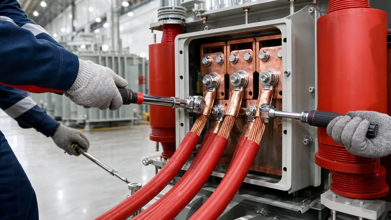
- Bolt terminations using Grade 8.8 high-tensile steel fasteners, pairing each bolt with a thick flat steel washer and a conical Belleville spring washer. Tighten to calibrated torque values (e.g., 45 Nm for M10, 85 Nm for M12 bolts) using a calibrated torque wrench.
- Observe mandatory minimum bending radii: single-core non-armoured XLPE power cables require a minimum dynamic bending radius of 12 to 15 times the overall external cable diameter.
Next steps: specifying and sourcing
When specifying and procuring power equipment, supplying precise terminal interface and conductor requirements to the factory prevents costly site rework. Ensure your request for quotation includes primary and secondary operating voltages, system fault level (kA and duration), required winding insulation class, cable entry orientation (top, bottom, or side terminal box), and terminal lug hole configurations (NEMA 2-hole or 4-hole patterns).
Explore our industrial range of high-efficiency dry type transformers, robust oil immersed transformers, and secure pad mounted transformers engineered to international IEC and IEEE specifications. For bespoke engineering submissions, tender drawings, and factory direct quotations, contact our engineering team via our quotation inquiry page.
Frequently asked questions
What size wire do I need for a transformer?
Wire size depends on the transformer full-load current multiplied by 1.25 for continuous loading, adjusted for ambient temperature, cable grouping, and short-circuit fault withstand. Calculate continuous current via I = S / (√3 × V), derate according to installation conditions, and cross-reference standard cable ampacity tables.
Can you use aluminium wire for transformer connections?
Yes, aluminium wire is widely used for both internal coils and external transformer cabling. However, aluminium requires roughly 1.6 times the cross-sectional area of copper to match ampacity, and external terminations must employ bi-metallic lugs with Belleville spring washers to counter galvanic corrosion and creep.
What is the difference between magnet wire and external transformer cable?
Magnet wire is internal winding wire coated with thin dielectric enamel or Nomex paper engineered to withstand high temperatures up to 220°C within tight core windows. External transformer cables feature heavy stranded conductors with extruded insulation like XLPE or EPR rated for 90°C distribution.
Why is the 125 percent factor required for transformer wire sizing?
The 125 percent factor is mandated by electrical codes such as NEC Article 450 to accommodate continuous non-linear operational loading, harmonic heating, and ambient variations without tripping upstream primary overcurrent devices or degrading conductor insulation over time.
How does ambient temperature affect transformer cable selection?
Elevated ambient temperatures reduce the rate at which cables dissipate resistive heat into the surroundings. When routing cables inside hot transformer marshalling enclosures or warm climates above standard 30°C ratings, derating factors must be applied to lower the cable's allowable current capacity.
What is the minimum bending radius for external transformer cables?
For low-voltage and medium-voltage power cables connecting to transformer terminals, the standard minimum bending radius is 8 to 12 times the cable overall diameter for unarmoured cables, and 12 to 15 times for armoured cables, preventing mechanical stress on bushings.
Tags: transformer wire cable for transformer transformer wiring cable sizing electrical engineering


