Key takeaways
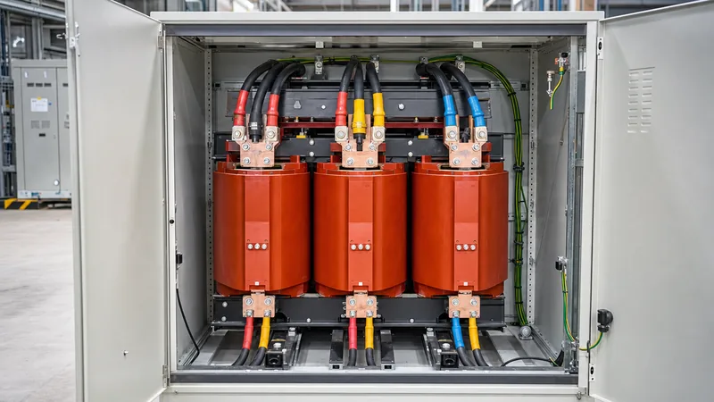
- Transformer primary terminals (H1, H2, H3) connect to the upstream source, while secondary terminals (X1, X2, X3, and neutral X0) supply the downstream load.
- Correct primary overcurrent protection must not exceed the limits set in NEC Article 450.3 or IEC 60364-4-43 to withstand initial inrush currents without nuisance tripping.
- Grounding continuity requires connecting the core, enclosure, and secondary neutral point (X0) to an earth electrode system with a resistance below 5 ohms per IEEE 142.
- Prior to energisation, insulation resistance tests between windings and from windings to earth must achieve values above 100 megohms at 1,000 V DC for low-voltage units.
- De-energised tap changers must only be adjusted when the unit is entirely isolated and discharged to match incoming distribution voltage variations.
Quick answer: To connect a transformer, first isolate and lock out all upstream electrical supplies. Verify voltage ratings against the nameplate, mechanically anchor the enclosure, land the high-voltage primary feed on terminals H1, H2, and H3, wire the low-voltage secondary output from terminals X1, X2, and X3 (plus neutral X0 if applicable), establish equipotential bonding to ground, and torque all hardware to manufacturer specifications.
Knowing how to hook up a transformer safely is critical for industrial power reliability and personnel protection. Whether deploying a dry-type distribution unit or a pad-mounted liquid-filled substation, an incorrect termination can trigger phase imbalance, flashover, or severe core saturation. This guide reviews site readiness, termination procedures, grounding rules, protection calculations, and pre-energisation testing.
Safety Clearances and Site Preparation: How to Install Transformer Enclosures
Site preparation determines the service life and operational safety of the equipment. Before moving a distribution unit onto its pad or plinth, engineers must verify minimum working clearances in accordance with local regulations, such as NFPA 70 (NEC Article 110.26) or IEC 61936-1 clause 7.
Ventilation clearances are critical. Dry-type units require an unobstructed distance of at least 150 mm to 300 mm from back and side walls to maintain natural convection through the enclosure louvres. For liquid-immersed units, liquid containment berms or drip trays must accommodate 100% of the dielectric liquid volume plus rainwater allowances. For heavier structural requirements, refer to our guide on industrial power system installation.
Follow this initial setup procedure to ensure stability before bringing conductors into the cabinet:
- Inspect the concrete foundation to ensure it is level within 3 mm per linear metre, fully cured, and clear of debris.
- Rig and crane the transformer using the designated lifting lugs; never pull or hoist using the winding bushings or radiator cooling fins.
- Place the unit onto anti-vibration neoprene pads or spring isolators to attenuate the transmission of 100 Hz or 120 Hz core hum into building structures.
- Anchor the frame to the concrete pad using grade 8.8 expansion bolts torqued to project engineering specifications.
- Verify that ambient temperature ratings adhere to IEC 60076-1 limits (maximum 40°C ambient, 30°C monthly average).
Step-by-Step Wiring: How to Hook Up a Transformer Safely
When executing the actual wiring, electricians must follow a disciplined step-by-step process to prevent mechanical strain on the terminations and guarantee dielectric integrity. High-voltage (HV) cables and low-voltage (LV) cables must enter the cabinet through dedicated cutouts, maintaining separation to eliminate capacitive coupling.
- De-energise and verify: Confirm isolation on all incoming medium-voltage or low-voltage feeders. Apply lock-out/tag-out (LOTO) padlocks, test with a calibrated, non-contact or contact voltage detector, and apply personal safety grounds.
- Prepare cable entries: Punch or cut conduit entries below terminal height to prevent moisture dripping from raceways directly onto energized live components. Install appropriate cable glands or conduits that preserve the enclosure NEMA or IP ingress rating.
- Strip and terminate conductors: Strip cable insulation using dedicated stripping tools without nicking strand cores. Crimp dual-hole or single-hole compression lugs using the correct hydraulic die and compression sequence.
- Connect primary windings: Bolt the line cables to high-side terminals (H1, H2, H3 for three-phase, or H1 and H2 for single-phase). Fit Belleville washers to maintain bolt tension across thermal expansion cycles.
- Connect secondary windings: Terminate load conductors onto low-side busbars or spade lugs (X1, X2, X3, and neutral X0). Ensure sufficient cable bend radius per IEEE 525 to avoid mechanical levering on terminal bushings.
- Torque to specification: Use a calibrated torque wrench on every electrical joint, applying torque values matching the hardware size (for example, 40 to 45 Nm for M10 high-tensile brass or steel fasteners), and mark each torqued bolt with torque seal paste.
For complex installations such as indoor substations, reviewing standard schematics in our transformer wiring schematic guide will help avoid crossed-phase errors.
Phase Matching and Terminal Identification: How to Connect Transformer Windings
Understanding terminal conventions and vector relationships is essential when learning how to connect transformer coils correctly. High-voltage terminals are consistently labelled with the letter H, while low-voltage terminals bear the designation X (and Y or Z on tertiary windings).
For standard three-phase systems, the most common configuration is a Delta-Wye (Dyn11 or Dyn1) setup. In this configuration, the primary delta winding connects line-to-line, while the secondary star winding establishes a neutral conductor derived from terminal X0. The vector group defines the phase angle displacement between the HV and LV line-to-neutral vectors (for example, 30 degrees electrical lead or lag). Connecting parallel transformers with mismatched vector groups results in massive circulating short-circuit currents that will trip upstream protective devices instantly.
Single-phase distribution units frequently provide dual secondary coils (marked X1, X2, X3, X4). Connecting X2 to X3 creates a series connection for 120/240 V split-phase service with a grounded neutral, whereas connecting X1 to X3 and X2 to X4 configures the unit in parallel for full capacity at 120 V single voltage.
Conductor, Fuse, and Protection Sizing Calculation
Sizing calculations ensure that supply conductors, secondary mains, and overcurrent protective devices (OCPD) operate safely within thermal limits while tolerating the magnetic inrush current, which can reach 10 to 12 times rated full-load amps for 100 milliseconds.
Consider a standard industrial example: a three-phase, 75 kVA dry-type transformer with a 480 V Delta primary and a 208Y/120 V secondary.
Step 1: Calculate primary full-load current ($I_p$):
$$I_p = \frac{S}{\sqrt{3} \times V_p} = \frac{75,000 \text{ VA}}{1.732 \times 480 \text{ V}} = 90.21 \text{ A}$$
Step 2: Size the primary overcurrent protection:
Per NEC 450.3(B) and standard industrial engineering practice, when only primary protection is provided without secondary OCPD, the maximum breaker rating is 125% of rated current. Where 125% does not correspond to a standard rating, the next standard size up is permitted (Table 240.6(A)):
$$90.21 \text{ A} \times 1.25 = 112.76 \text{ A} \rightarrow \text{Next standard breaker size: } 125 \text{ A}$$
Step 3: Calculate secondary full-load current ($I_s$):
$$I_s = \frac{S}{\sqrt{3} \times V_s} = \frac{75,000 \text{ VA}}{1.732 \times 208 \text{ V}} = 208.18 \text{ A}$$
Step 4: Size the secondary overcurrent protection and conductors:
If secondary protection is implemented at the main panelboard, a standard 250 A or 125% maximum rated breaker (260.2 A, selecting a 250 A trip unit) protects the secondary bus. Copper conductors must be rated at 75°C to match equipment terminal lugs: selecting 250 kcmil copper provides an ampacity of 255 A, adequately covering continuous load requirements.
Grounding and Bonding Rules for Separately Derived Systems
Transformer grounding stabilizes system voltage relative to earth during normal operation and clears phase-to-ground faults rapidly. A delta-wye transformer creates a separately derived system under electrical codes.
To bond this system properly, three connections must be made within the transformer or the first downstream disconnect:
- System Bonding Jumper: Connects secondary neutral point X0 to the transformer metal enclosure using an appropriately sized copper conductor (sized per NEC Table 250.102(C)(1)).
- Grounding Electrode Conductor (GEC): Connects X0 and the enclosure to the facility earth electrode grid (building steel, driven ground rods, or foundation rebar). Earth resistance must not exceed 5 ohms in industrial substations per IEEE 142 recommendations.
- Equipment Grounding Conductor (EGC): High-voltage supply conduits and equipment grounding wires must bond directly to the internal cabinet grounding lug to ensure a low-impedance return fault path back to the source substation.
Pre-Commissioning Inspection and Acceptance Testing
Before closing the primary switch, comprehensive electrical testing confirms winding insulation condition, turns ratio correctness, and mechanical tightness. Never energise a transformer based on visual inspection alone. For detailed electrical test procedures, consult our technical resource on how to test a transformer.
Use the following acceptance matrix before final energisation:
| Inspection / Test Parameter | Governing Standard | Test Instrument / Method | Acceptable Criteria |
|---|---|---|---|
| Insulation Resistance (Megger) | IEEE C57.12.91 clause 10.11 | 5 kV DC (HV), 1 kV DC (LV) | > 100 MΩ at 20°C normalised |
| Winding Resistance | IEC 60076-1 clause 11.2 | Micro-ohmmeter / Kelvin bridge | Phase deviation within ±2% of average |
| Voltage Turns Ratio (TTR) | IEEE C57.12.90 clause 6 | Digital TTR Test Set | Within ±0.5% of calculated nameplate ratio |
| Polarity & Vector Verification | IEC 60076-1 clause 11.4 | Direct DC / Oscilloscope / TTR | Correct phase displacement (e.g. 30° lag) |
| Torque Audit | Manufacturer Spec | Calibrated mechanical torque wrench | 100% joints verified against torque table |
| Dielectric Liquid Breakdown | ASTM D877 / IEC 60156 | Oil dielectric test cell | > 30 kV (new oil prior to energising) |
After testing passes, verify off-circuit tap changer positions. Ensure the tap switch is locked in the position that matches average utility grid voltage before closing the upstream circuit breaker.
Next steps: specifying and sourcing
When preparing technical bid documents or purchasing transformers for commercial, municipal, or utility projects, clear parameters prevent installation mismatches. Outline total kVA capacity, primary and secondary voltages, winding materials (copper or aluminium), impedance voltage (%Z), basic impulse insulation level (BIL), and vector groups in your technical schedule.
Explore our selection of dry-type transformers for indoor commercial installations, or examine our oil-immersed transformers for external utility distribution. For complete turnkey power equipment packages, submit your single-line diagram (SLD) directly on our transformer quotation page or speak with our application engineers via the contact page.
Frequently asked questions
how to hook up a transformer
To hook up a transformer, isolate the upstream supply, secure the enclosure to its foundation, terminate the high-voltage lines on terminals H1, H2, and H3, terminate low-voltage load lines on X1, X2, X3, and X0, bond the neutral and chassis to the earthing electrode, and torque all connections to specified mechanical ratings.
how to connect transformer
Connecting a transformer requires matching the supply phase lines to high-side terminals (H1, H2, H3) and matching secondary outputs (X1, X2, X3, X0) to load distribution panels. Ensure phase rotation matches (A-B-C) and connect tap switch positions according to measured line voltage before applying power.
how to install transformer
To install a transformer, mount the unit onto a level concrete pad with anti-vibration dampeners, leave appropriate ventilation clearance around enclosure walls, land conduits through bottom or side entry plates, install grounding conductors to building steel or earth rods, and complete insulation resistance and winding ratio tests before energisation.
What size wire do I need to connect a 75 kVA transformer?
For a 480 V primary, a 75 kVA unit draws approximately 90 A full-load, requiring 1 AWG copper conductors protected by a 125 A breaker. On a 208 V secondary, full-load current is 208 A, requiring 250 kcmil copper conductors rated for 75°C terminations.
Do you bond the neutral to ground inside a step-down transformer?
Yes, on a step-down transformer secondary configured as a separately derived wye system, terminal X0 must bond to the transformer chassis and to a grounding electrode conductor using an appropriately sized system bonding jumper, unless bonded at the first disconnect.
Why is phase rotation testing necessary before connecting loads?
Phase rotation testing verifies that secondary output phases sequence in standard clockwise order (A-B-C). Incorrect phase rotation will cause three-phase induction motors to spin in reverse, risking severe mechanical equipment damage.
Tags: how to hook up a transformer how to connect transformer how to install transformer transformer wiring electrical commissioning


