Key takeaways
- Industrial power system installation demands rigid structural plinth tolerances within plus or minus 1 mm per metre to avoid medium-voltage busbar misalignment.
- Unlike commercial power distribution networks, industrial systems require fault withstand ratings capable of handling high inductive motor contributions and low power factor transient loads.
- A 2,500 kVA, 11 kV to 400 V transformer with 6.0% impedance produces a prospective symmetrical short-circuit current of 60.14 kA at its secondary terminals.
- Earthing grid installations governed by IEEE 80 require step and touch voltage verification through fall-of-potential testing before plant energisation.
- Pre-commissioning insulation resistance testing for 11 kV switchgear requires a minimum insulation threshold of 1,000 megohms using a 2.5 kV DC test set.
Quick answer: An industrial power system installation encompasses the engineering, civil foundations, structural rigging, cabling, protection coordination, and energisation of high-to-low voltage electrical infrastructure supplying heavy manufacturing or processing facilities. Executing this process safely requires adherence to international standards such as IEC 61936-1 and IEEE 3001.5 to manage severe thermal, short-circuit, and mechanical stresses.
Industrial plants impose demanding duty cycles on electrical distribution assets. Continuous processing lines, dynamic motor starts, non-linear harmonic loads, and severe arc-flash risks differentiate these facilities from basic commercial installations. Whether installing a new factory supply or expanding an existing primary intake, adhering to precise geometric alignments, correct torque specifications, and disciplined commissioning stages determines long-term equipment reliability.
Standards and Codes Governing Industrial Power System Installation
Regulatory compliance provides the baseline engineering envelope for safety, clearance distances, and fault withstand capability. An industrial power system installation must comply with structural, environmental, and operational mandates enforced by regional and global authorities.
In international projects adhering to the International Electrotechnical Commission framework, IEC 61936-1 dictates power installations exceeding 1 kV AC. This standard specifies minimum phase-to-phase and phase-to-earth electrical clearances in air (for example, 270 mm clearance for 33 kV systems under standard BIL ratings). Enclosed medium-voltage equipment must meet IEC 62271-200 criteria for metal-enclosed switchgear, governing internal arc classifications (IAC AFLR) to protect operating personnel from blast energies.
For projects following North American practices, NFPA 70 (National Electrical Code, NEC) Article 450 governs transformer vaults, ventilation paths, and overcurrent thresholds, while Article 490 covers equipment operating over 1,000 volts. Furthermore, IEEE 3001.5 establishes the recommended practice for the application of power distribution apparatus in industrial installations, detailing how continuous loads, dynamic switching, and environmental ingress dictate physical housing parameters.
Industrial Power Systems vs Commercial Power Distribution
Understanding the operational divergence between industrial facilities and commercial buildings is essential when sizing switchgear and configuring distribution networks. While commercial power distribution prioritises occupant safety, quiet operation, and aesthetic integration, industrial facilities prioritise run-time availability, short-circuit endurance, and selective fault isolation.
Commercial buildings, such as corporate offices and retail centres, operate on predictable diurnal load cycles with power factors typically corrected above 0.95 through distributed building automation. Fault levels remain moderate, rarely exceeding 25 kA to 50 kA on the low-voltage side. In contrast, industrial power systems feed high-inertia induction motors, variable-frequency drives (VFDs), and arc furnaces that introduce significant harmonic distortion and severe transient overvoltages.
| Design Parameter | Industrial Power System | Commercial Power Distribution |
|---|---|---|
| Nominal Intake Voltage (kV) | 11 kV, 22 kV, 33 kV, up to 110 kV | 400 V up to 11 kV / 22 kV |
| LV Fault Level (kA, 1s rms) | 50 kA to 100 kA | 25 kA to 50 kA |
| Redundancy Architecture | Main-Tie-Main (2N), Secondary Selective | Radial or Single-Tie Ring |
| Harmonic Profile (THD-V / THD-I) | High (THD-I frequently exceeds 15%) | Low to Moderate (THD-I under 5-8%) |
| Switchgear Ingress Protection | IP54 to IP65 (dust, moisture, chemical) | IP31 to IP41 (standard conditioned indoor) |
| Busbar Construction | Hard-drawn copper, high bracing index | Copper or aluminium, standard bracing |
Primary Substation and Switchgear Rigging & Foundation
The civil and structural foundation forms the physical baseline of every industrial power system installation. Misaligned concrete plinths inevitably induce mechanical stress on draw-out circuit breaker interlocks, busbar disconnect points, and fluid containment seals.
Civil teams must finish switchgear plinths to a strict flatness tolerance: no more than a 1 mm deviation per linear metre, and a maximum total level deviation of 2 mm across the entire switchboard run. Before rigging panels into position, base channels must be grouted and welded or chemically anchored to embedded steel plates according to the manufacturer's floor plan drawings. When maneuvering heavy unit substation modules or medium-voltage metal-clad enclosures, rigging crews should use synchronised hydraulic jacks, machinery skates, or spreader bars designed for overhead crane lifts to prevent frame torsion.
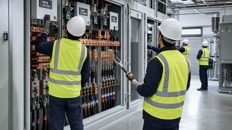
Once placed, join adjacent cubicles starting from the central shipping split outward. Torque high-strength structural connection bolts to manufacturer values before bolting horizontal busbars. For M12 grade 8.8 busbar bolts, apply 70 Nm to 85 Nm using calibrated torque wrenches, followed by a permanent witness paint mark across the bolt head, washer, and busbar to indicate inspected tightness.
Transformer Sizing and Short-Circuit Calculation
Specifying transformer capacity and calculating prospective short-circuit currents ensures protective devices interrupt faults before catastrophic equipment damage occurs. In an industrial power system installation, step-down transformers must accommodate steady-state loading, motor starting voltage dips, and prospective thermal stresses.
Consider an industrial manufacturing facility requiring a continuous apparent power demand of 1,850 kVA. Sizing with an 80% maximum steady-state loading target to allow for future expansion yields:
Required Sizing: Srated = 1,850 kVA / 0.80 = 2,312.5 kVA. An engineer selects a standard 2,500 kVA, three-phase oil-immersed or cast resin transformer stepping down from 11 kV to 400 V line-to-line (0.4 kV), with an impedance voltage (%Z) of 6.0% and an X/R ratio of 8.0.
The secondary nominal full-load current (IFL) is calculated as:
IFL = Srated / (√3 × VLL) = 2,500 kVA / (1.732 × 0.4 kV) = 3,608.4 A
Assuming an infinite medium-voltage utility bus (conservative worst-case screening per IEC 60909-0), the prospective symmetrical three-phase short-circuit current (ISC) at the 400 V switchgear incoming terminals is:
ISC = IFL / (Z% / 100) = 3,608.4 A / 0.06 = 60,140 A = 60.14 kA
The main low-voltage circuit breaker and switchboard busbar assembly must therefore possess a rated short-time withstand current (Icw) of at least 65 kA for 1 second, and a peak withstand rating (Ipk) determined by the peak factor κ:
κ = 1.02 + 0.98 × e(-3 / (X/R)) = 1.02 + 0.98 × e(-3 / 8) = 1.02 + (0.98 × 0.6873) = 1.693
Ipk = √2 × κ × ISC = 1.414 × 1.693 × 60.14 kA = 143.97 kA
All upstream protective releases, busbars, and downstream distribution boards must be rated to clear or withstand these electrodynamic forces without mechanical deformation.
Medium and Low-Voltage Cable Installation Protocols
Cable system failures represent the most common cause of unscheduled outages during industrial power system installation and startup. Rigorous adherence to pulling tension limits, minimum bend radii, and testing procedures prevents premature breakdown of the dielectric insulation.
For medium-voltage cables (e.g., 11 kV to 33 kV single-core or three-core cross-linked polyethylene, XLPE), the minimum bending radius during laying is typically 15 to 20 times the cable overall diameter (OD) in accordance with IEC 60502-2. Pulling calculations must respect the manufacturer's maximum pulling tension on the copper conductor, conventionally rated at 50 N/mm² for copper cores pulled by pulling eyes, or 5 N/mm² when using cable grips over the outer sheath. Install calibrated dynamometers on pulling winches to record continuous line tension.
Terminate MV cables using heat-shrink or cold-shrink termination kits in strict compliance with the manufacturer's cutback dimensions. Maintain exact stripping dimensions for the semi-conductive layer to prevent electric field concentration at the screen cut. After termination, verify installation integrity using Very Low Frequency (VLF) AC withstand testing at 0.1 Hz per IEEE 400.2 standards (typically applying 2 to 3 times nominal phase-to-ground voltage for 15 to 60 minutes) combined with Tan Delta or partial discharge diagnostic analysis.
Grounding Grid Design and Earth Potential Rise Mitigation
An earthing system provides a low-impedance dissipation path for lightning surges, phase-to-earth fault currents, and static electricity, while limiting touch and step voltages to tolerable human safety thresholds. Proper grounding design is a foundational element of any industrial power system installation.
Governed by IEEE 80 (Guide for Safety in AC Substation Grounding) or IEC 61936-1 Annex B, the grounding system consists of a buried grid of bare copper conductors (typically 70 mm² to 120 mm² stranded copper or copper-bonded steel) interconnected via exothermic welds at all crossing junctions. Vertical earth rods (5/8 inch or 3/4 inch diameter, 3 metres long) are driven into the soil at peripheral nodes to penetrate low-resistivity subsoil layers.
Touch voltage (Etouch) and step voltage (Estep) must not exceed permissible limits calculated from body weight and the surface layer resistivity (e.g., a 100 mm to 150 mm thick crushed rock gravel layer with a wet resistivity around 3,000 Ω·m). Before any switchgear or transformer is connected, test the overall grid resistance to remote earth using the fall-of-potential method (four-lead Wenner configuration). In industrial sites, target a total system resistance to earth of less than 1.0 Ω (often specified under 0.5 Ω for heavy industrial process plants).
Step-by-Step Industrial Power System Installation and Energisation
A disciplined energisation procedure prevents unexpected tripping, arc flashes, and equipment destruction. Follow this chronological, safety-verified execution sequence:
- Civil Handover and Environmental Verification: Inspect substation rooms for structural completion, overhead watertightness, operational HVAC, and clean cable trenches before moving electrical gear inside.
- Equipment Placement and Mechanical Anchoring: Uncrate, position, and torque all primary distribution equipment, including IEC 61439 compliant switchboards, transformers, and switchgear to civil plinths.
- Busbar Bolting and Torque Marking: Align shipping splits, torque copper joints using calibrated torque tools, verify mechanical clearances, and apply permanent inspection witness lines.
- Cable Pulling, Glanding, and Termination: Route primary and secondary feeder cables, terminate conductors, attach earthing braids to ground buses, and install fire-stopping barriers at wall penetrations.
- Cold Pre-Commissioning Electrical Testing: Perform insulation resistance, contact resistance (micro-ohmmeter), current transformer (CT) polarity, ratio, and secondary burden tests, as well as relay secondary injection testing per the substation testing guide.
- Interlock and Control Logic Verification: Function-test all electrical, key-exchange, and mechanical interlocks across circuit breakers, disconnectors, and earth switches.
- Pre-Energisation Safety Walkdown: Issue work permits, clear all tools, vacuum enclosures to remove metal debris, verify panel covers are secured, and lock out un-energised circuits.
- No-Load Primary Energisation: Close the primary incoming MV supply breaker, observe system voltage indicators, confirm balanced phase voltages, and verify correct phase rotation (standard phase sequence).
- Transformer Inrush and Soak Period: Energise step-down power transformers under zero load for a mandatory 24-hour soak period, continuously monitoring acoustic signatures, pressure release devices, and oil/winding temperatures.
- Stepwise Load Pickup: Progressively close outgoing feeder breakers, starting with non-critical distribution and proceeding to large motor loads, monitoring voltage stability and thermal balance under running current.
Quality Control Checklist for Industrial Power System Installation
This quality control checklist serves as an inspection and verification standard for site engineers and contractors prior to signing off on an industrial power system installation.
| Inspection Area | Specific Quality Check | Acceptance Criteria | Reference Standard |
|---|---|---|---|
| Switchgear Housing | Internal debris inspection & vacuuming | Zero metallic dust, debris, or moisture; IP rating verified | IEC 62271-200 |
| Main Busbar System | Micro-ohm contact resistance across joints | Within 10% of factory test report baseline; torque marked | IEC 61439-1 |
| Insulation Resistance | 11 kV busbars to earth / phase-to-phase | ≥ 1,000 MΩ using 2.5 kV DC test set for 1 minute | IEEE 43 / NETA MTS |
| Transformer Auxiliary | Buchholz, temperature probe, PRD signals | 100% trip/alarm contact activation verified at relay | IEC 60076-1 |
| Earthing Connections | Earth bar continuity across all cubicle frames | < 0.1 Ω resistance from frame to main station earth ring | IEEE 80 |
| Protection Relays | Secondary injection verification of settings | Tripping curves within ±5% of coordinated study curves | IEEE C37.90 |
| Cable Terminations | Phase rotation and VLF withstand check | Correct clockwise rotation; zero breakdown at 3U0 for 15 min | IEEE 400.2 |
Next steps: specifying and sourcing
Executing an industrial power system installation on schedule requires close alignment between process load requirements, civil milestones, and factory lead times. To initiate equipment sizing or obtain an engineering quotation, compile your single-line diagrams (SLD), fault level calculations, utility connection voltages, ambient site profiles, and protection coordination philosophy. Review our heavy-duty HV/LV switchgear solutions and integrated transformer substations designed for harsh operating environments. Contact our engineering team directly through our contact page or submit your technical specifications through our quote page to receive comprehensive application support.
Frequently asked questions
What is an industrial power system installation?
An industrial power system installation is the turnkey electrical infrastructure that receives high or medium voltage from a utility, steps it down, and distributes safe, reliable power across heavy manufacturing, process, or production facilities.
How does an industrial power system differ from commercial power distribution?
Industrial systems feature higher fault-current ratings, severe inductive and non-linear motor loads, redundant architectures (like Main-Tie-Main), and ruggedised enclosures, whereas commercial distribution focuses on lower fault levels, quiet operation, and light diurnal lighting or HVAC profiles.
What is the acceptable flatness tolerance for switchgear foundation plinths?
The foundation plinth must have a flatness tolerance within plus or minus 1 mm per linear metre, with a maximum cumulative deviation of no more than 2 mm across the entire length of the switchgear lineup.
Why is a 24-hour transformer soak period necessary before loading?
A 24-hour no-load soak verifies core and insulation stability under full operating magnetic flux. It confirms normal oil circulation, acoustic levels, and ensures auxiliary trip devices like Buchholz relays and pressure relief valves do not trigger under inrush or thermal equilibrium.
What is the minimum insulation resistance acceptable for 11 kV switchgear before energisation?
For 11 kV medium-voltage switchgear, a minimum insulation resistance of 1,000 megohms (MΩ) tested at 2.5 kV DC for 60 seconds is the standard field acceptance threshold before primary energisation.
What testing standard governs medium-voltage VLF cable testing on site?
IEEE 400.2 governs field testing of shielded medium-voltage cable systems using Very Low Frequency (0.1 Hz) AC withstand voltages, combined with Tan Delta or partial discharge measurements.
Tags: industrial power system installation commercial power distribution substation engineering switchgear commissioning power distribution


