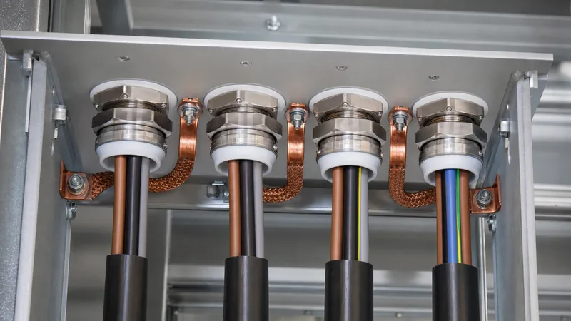
Key takeaways
- An electrical box bushing provides mechanical edge protection and dielectric clearance where conductors pass through metal enclosure walls or knockout openings.
- National Electrical Code (NEC) 300.4(G) mandates smooth, rounded insulating bushings for conductors sized 4 AWG (21.2 mm²) or larger passing into enclosures.
- Material selection between zinc-plated malleable iron, engineered thermoplastic, and aluminium depends on environmental corrosion classes and mechanical fault ratings.
- Maintaining enclosure ingress protection (IP54 to IP66 / NEMA 3R to 4X) requires coordinated locknut torques and integrated neoprene or elastomeric sealing rings.
- Panel clearance design must account for conductor bending radiuses according to NEC Table 312.6(A) and IEC 61439 creepage and clearance distances.
Quick answer: An electrical box bushing is a threaded or snap-in fitting installed at an enclosure knockout or conduit entry to protect cable insulation from sharp metallic sheet edges, prevent mechanical abrasion during thermal expansion, and ensure electrical safety compliance. For conductors sized 4 AWG (21.2 mm²) or larger, standards such as NEC 300.4(G) legally mandate an insulating surface to prevent phase-to-earth faults.
In industrial power distribution, switchgear marshalling enclosures, and distribution transformer cable boxes, terminating conductors without proper entry fittings introduces critical failure points. Sheet metal edges from stamped or laser-cut knockouts carry microscopic burrs that pierce polyvinyl chloride (PVC), cross-linked polyethylene (XLPE), or ethylene propylene rubber (EPR) insulation over repeated thermal load cycles. Specifying the correct fitting safeguards the installation against severe ground faults, maintains structural integrity, and ensures compliance with global electrical safety directives.
For broader context on high-voltage and medium-voltage transformer termination hardware, refer to our Transformer Bushing Guide: Engineering, Types & Testing.
What Is an Electrical Box Bushing and Where Is It Required?
An electrical box bushing is an engineered mechanical termination fitting designed to sit between a conductor's outer insulation and the raw metallic rim of an enclosure knockout, conduit stub, or gland plate.
Under both international standards (such as IEC 61439-1 clause 8.8) and North American frameworks (such as NFPA 70 / NEC Article 300.4(G)), uninsulated metal edges are recognised as continuous mechanical hazards. When medium-voltage or low-voltage conductors carry load currents, cyclical thermal expansion and electromagnetic forces cause minute physical movement. Over time, these movements press the cable sheath against the sharp boundary of the wall entry. Without a radiused fitting, the sheath ruptures, resulting in direct copper-to-chassis flashovers.
Key installation locations include:
- Transformer cable terminal boxes: Transition points where low-voltage winding leads leave the transformer tank enclosure to enter dry marshalled marshalling boxes or secondary panels, often addressed alongside specialised 2-inch plastic bushings for auxiliary feeds.
- Substation distribution cubicles: Conduit penetrations entering top or bottom gland plates in packaged unit substations and power conditioning houses.
- Industrial switchgear: Low-voltage control wire bundles and power feeder raceways terminating into sections governed by IEC 61439 low-voltage switchgear standards.
Electrical Panel Bushing vs Electrical Box Bushing: Materials and Types
Choosing between an electrical panel bushing and a standard electrical box bushing depends primarily on enclosure fault capacity, vibration profiles, and chemical or outdoor exposure.
The term electrical panel bushing typically denotes high-integrity, heavy-duty fittings utilised on switchboards, industrial control panels, and motor control centres (MCCs), whereas box bushings encompass standard conduit fittings utilised across general pull boxes and junction enclosures. Selecting the correct material is vital to match mechanical shock, ambient ultraviolet (UV) radiation, and chemical atmospheres.
| Material Type | Typical Tensile Strength (MPa) | Temperature Rating (°C) | Dielectric Strength (kV/mm) | Primary Application |
|---|---|---|---|---|
| High-Impact Polypropylene / Nylon | 35 – 70 | -40 to +105 | 15 – 25 | Standard junction boxes, auxiliary low-voltage cabinets, dry indoor raceways |
| Malleable Iron (Zinc Plated) | 300 – 380 | -50 to +150 | Conductive (requires insulating throat) | Rigid metal conduit (RMC), high-vibration equipment, explosion-proof entries |
| Die-Cast Zinc Alloy | 250 – 280 | -40 to +120 | Conductive (plastic throat insert) | Commercial panel entries, intermediate metal conduit (IMC), EMT terminations |
| Cast Aluminium (Copper-Free) | 170 – 240 | -50 to +150 | Conductive (throat insulated) | Marine environments, chemical processing, outdoor coastal transformer boxes |
For installations carrying high fault levels, grounding-type insulated bushings are mandatory. These fittings integrate a tin-plated aluminium or copper lay-in lug (rated per UL 467 and CSA C22.2 No. 41) that bonds the rigid conduit line directly to the enclosure's main protective earth conductor, preventing transient step-and-touch potentials during earth fault clearance times.
Engineering Sizing and Clearance Calculations for Box Bushings
Sizing an electrical box bushing requires aligning conduit trade dimensions, conductor overall diameters, enclosure entry clearances, and minimum wire-bending spaces.
According to NEC 312.6(A) and IEC 60947-1, terminal enclosures must provide adequate depth so cables entering through a box bushing do not bend at an angle sharper than their manufacturer-specified minimum bending radius (typically 8× to 12× overall cable diameter for non-shielded armoured power cables). The internal bore of the chosen electrical box bushing must also allow adequate cross-sectional area to respect the 40% raceway fill limit for three or more conductors (per NEC Chapter 9, Table 1).
Consider this practical calculation for a three-phase low-voltage feeder entering a bottom marshalling enclosure:
- Specified Cable: Four single-core 300 mm² (approx. 600 kcmil) copper XLPE conductors.
- Cable Outer Diameter ($D_c$): 30.2 mm per conductor.
- Total Conductor Cross-Sectional Area: $4 \times \pi \times (30.2 / 2)^2 = 4 \times 716.3 = 2,865.2 \text{ mm}^2$.
- Required Conduit Internal Area at 40% Fill: $2,865.2 / 0.40 = 7,163 \text{ mm}^2$.
- Internal Conduit Diameter Required: $\sqrt{(4 \times 7,163) / \pi} = 95.5 \text{ mm}$ (demanding a 4-inch / DN100 conduit trade size).
- Bushing Bore Verification: A standard 4-inch metallic conduit insulated bushing provides a nominal throat clearance diameter of 97.8 mm. This clearance allows the four 30.2 mm cables to slide smoothly past the radiused insulated lip without binding against the steel locknut threads.
- Wall Clearance Clearance ($C$): To prevent uninsulated sheet contact, the outer flange of the electrical box bushing must overlap the knockout hole by at least 3.2 mm around the entire circumference. For a standard 4-inch knockout ($111.1 \text{ mm}$ diameter), the bushing flange outer diameter must equal or exceed $117.5 \text{ mm}$.
Step-by-Step Installation and Gasket Sealing Guidelines
Installing an electrical box bushing correctly requires systematic mechanical alignment, torque control, and verification of environmental sealing.
- De-burr and Clean the Knockout: Clear all punching burrs, metallic shavings, and paint residue from the perimeter of the panel entry hole. Sharp metal edges can puncture internal sealing gaskets during tightening.
- Position the Ingress Gasket: When maintaining IP56, IP66, or NEMA 4X enclosure integrity, position a closed-cell neoprene or fluorosilicone sealing ring onto the male-threaded conduit end or the exterior entry boss before inserting it into the enclosure wall.
- Thread the Primary Enclosure Locknut: Spin the exterior locknut until it sits flush against the enclosure sheet. Ensure the teeth or serrations penetrate non-conductive surface paint to establish metal-to-metal contact for electrical continuity.
- Thread the Electrical Box Bushing: Thread the insulated electrical panel bushing onto the protruding male threads inside the panel. Hand-tighten until the internal insulating lip seats completely against the conduit edge, covering all raw male threads.
- Apply Final Calibration Torque: Using a calibrated torque wrench and spanner adapter, torque the fitting according to trade sizing: 1/2-inch to 1-inch fittings require 35 Nm; 1-1/4-inch to 2-inch fittings require 50 Nm; 2-1/2-inch to 4-inch fittings require 70 to 85 Nm. Do not over-torque, as over-tightening can split plastic collars or strip aluminium threads.
- Bond the Earth Lug (if applicable): For grounding-style bushings, insert the bare copper bonding jumper into the mechanical lug and torque the set screw to manufacturer ratings (typically 5.6 Nm for 14–4 AWG screws and 9.0 Nm for larger terminals). Route the jumper directly to the cabinet ground bar with minimum slack.
Common Failure Modes and Site Inspection Checklist
Field failures involving an electrical box bushing typically stem from mechanical over-tightening, thermal fatigue, or poor selection for the chemical environment.
During periodic maintenance or factory acceptance testing (FAT), inspect enclosure cable penetrations against the following engineering criteria:
- Cracked or Missing Insulating Throats: Standard cheap nylon or phenolic collars degrade under excessive ultraviolet radiation or extreme enclosure temperatures ($>90^\circ\text{C}$). A shattered collar exposes the conductor directly to bare zinc-plated threads.
- Loss of Electrical Continuity: On ungrounded locknut configurations, panel vibration caused by nearby transformers or rotating machinery can loosen locknuts, interrupting the earth fault return path.
- Water and Particulate Ingress: Gasket deformation from excessive torque ruptures the seal, causing moisture entry that reduces insulation resistance across the terminal board.
Use this field inspection checklist for plant audits and retrofits:
| Inspection Parameter | Verification Method | Acceptance Standard |
|---|---|---|
| Insulation Collar Integrity | Visual / tactile inspection around 360° of bore | Zero cracks, zero deformation; smooth radiused profile intact |
| Thread Coverage | Visual inspection of internal conduit projection | Conduit threads fully masked; zero exposed male threads inside box |
| Locknut Mechanical Tightness | Mechanical torque audit with calibrated wrench | Meets target torque ($35 – 85 \text{ Nm}$ based on conduit trade size) |
| Grounding Lug Torque | Calibrated screw-torque driver check | Conductor firmly seated with zero strand slippage under 5–9 Nm |
| Cabinet Ingress Integrity | Chalk or feeler gauge check along gasket boundary | Full circumference gasket compression without extrusion |
Next steps: specifying and sourcing
When preparing requests for quotation (RFQs) or engineering design packages for industrial power equipment, clearly define your enclosure entry parameters. State the exact conduit trade size, sheet metal thickness, ingress protection requirements (such as IP55, IP66, or NEMA 4X), and fault-current bonding ratings. Whether you are outfitting high-performance HV/LV switchgear, specifying secondary junction boxes on pad-mounted transformers, or planning medium-voltage entries for transformer substations, our engineering application team can provide verified drawings, thermal compatibility schedules, and custom termination packages. Contact our design office directly or submit your project schedules via our online quotation portal to receive technical documentation and pricing.
Frequently asked questions
Why is an electrical box bushing mandatory for conductors 4 AWG and larger?
An electrical box bushing is legally mandatory under NEC 300.4(G) because heavy conductors (4 AWG / 21.2 mm² or larger) exert substantial mechanical pressure on enclosure entry boundaries. Without a smooth, radiused insulating collar, natural vibration and thermal load cycling force the sharp sheet metal or conduit threads to cut into the conductor insulation, creating dangerous short circuits.
Can I use an all-plastic electrical box bushing on metal enclosures?
Yes, you can use an all-plastic electrical box bushing on metal enclosures provided that the raceway system does not rely on the bushing itself to maintain electrical continuity. If rigid metal conduit requires grounding bonding at that penetration, an insulated metallic grounding bushing with an integrated bonding lug must be used instead.
What is the difference between a conduit bushing and a cable gland?
A conduit bushing threads onto conduit pipe stubs or threaded hub entries to provide a protective, rounded lip for conductors pulling into a box. A cable gland mechanically clamps the outer jacket of an unarmoured or armoured cable directly, providing complete environmental sealing (high ingress protection ratings), strain relief, and electrical earth continuity across the entry wall.
How do you maintain NEMA 4X or IP66 ratings when using a box bushing?
To maintain NEMA 4X or IP66 ratings, you must use a threaded hub fitting or an electrical box bushing assembly equipped with an elastomeric sealing ring seated on the enclosure exterior. The locknut must be torqued to manufacturer specifications against a flat, clean enclosure surface to achieve continuous gasket compression.
What material is recommended for an electrical panel bushing in corrosive atmospheres?
For corrosive, coastal, or chemical environments, copper-free cast aluminium or 316 stainless steel bushings with UV-stabilised engineered thermoplastic insulating throats are recommended. Standard zinc die-cast fittings oxidise rapidly in salt-spray or high-humidity conditions, compromising mechanical retention and ingress sealing over time.
Tags: electrical box bushing electrical panel bushing transformer bushings cable gland enclosure engineering


