Key takeaways
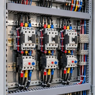
- An MCC bucket typically holds a disconnect or motor circuit protector, contactor, overload relay, control transformer, pilot devices and terminal blocks for one motor.
- NEMA starter Size 1 handles 10 hp, Size 3 handles 50 hp and Size 5 handles 200 hp at 460 V, which sets bucket height and space use.
- NEC 430.24 sizes MCC feeders and bus at 125 percent of the largest motor full-load current plus the sum of all other motor currents.
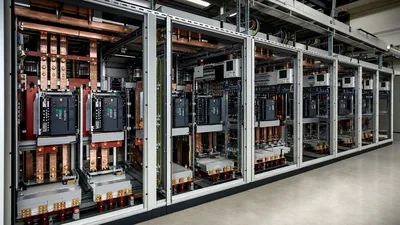
- IEC 61439-2 MCCs use Form 3b or Form 4b separation with withdrawable units and Type 2 coordination per IEC 60947-4-1 to allow fast replacement after faults.
- NEC 110.26 requires 3 to 4 ft of working space at a 480 V MCC, plus two entrances for equipment of 1,200 A or more over 6 ft wide.
Quick answer: A motor control center (MCC) is a floor-standing assembly of vertical sections sharing a common power bus, each holding plug-in or withdrawable units called buckets that contain the starter, protection and control for one motor. MCCs centralize motor control for plants with many motors, and are built to UL 845 and NEMA ICS 18 in North America or IEC 61439-2 elsewhere.
A process plant, water treatment works or mine may run hundreds of motors. Feeding each from its own wall-mounted starter scatters protection, wiring and maintenance across the site. A motor control center gathers them into one line-up in one room, with a common bus, standard plug-in units and a single point for monitoring and lockout.
This guide is for electrical engineers, maintenance managers and procurement teams specifying or upgrading MCCs. It defines MCC terminology, breaks down a bucket, compares NEMA and IEC construction, works through bus sizing, and covers room layout and arc-flash measures. The individual starter technologies inside the buckets are covered in our motor starter types guide.
What Is a Motor Control Center?
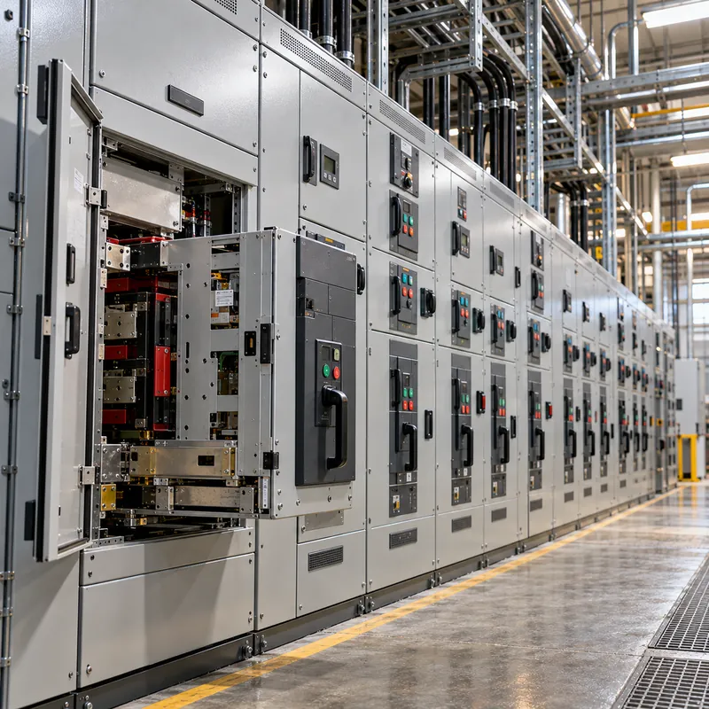
In electrical terms, MCC stands for motor control center: an assembly of one or more enclosed vertical sections with a common power bus, principally containing motor control units. That is the definition used by UL 845 and NEMA ICS 18, and it separates an MCC from a switchboard (which distributes power to feeders) and from a control panel (which holds logic and small devices).
The physical structure of a typical North American MCC:
- Vertical sections, commonly about 20 in (508 mm) wide and 90 in (2,286 mm) high, bolted together into a line-up.
- Horizontal bus running through the top or middle of every section, typically 600 to 3,200 A copper, tin- or silver-plated.
- Vertical bus in each section, commonly 300 to 600 A, into which bucket stabs plug.
- Units (buckets) stacked in each section, each behind its own door.
- Wireways: a vertical wireway beside the units and horizontal wireways top and bottom for load and control cables.
- Incoming section with main lugs, main breaker or fused switch.
An electrical motor control center can also contain feeder breakers, lighting transformers, panelboards, PLC sections and VFDs, making it a compact plant distribution hub. The main supply usually comes from the plant's main distribution board or directly from a unit substation transformer.
MCC Bucket Components: What Is Inside a Motor Control Bucket?
An MCC bucket is a removable unit that contains all equipment needed to control and protect one motor or feeder. It plugs onto the vertical bus with spring-loaded stabs and is locked in place, so it can be withdrawn and replaced without de-energizing the rest of the line-up. Typical MCC bucket components:
- Disconnect: a motor circuit protector (instantaneous-only breaker), thermal-magnetic breaker or fused switch, operated by a door-mounted handle that is interlocked with the door.
- Contactor rated by NEMA size or IEC AC-3 current.
- Overload relay: bimetallic, or more often electronic with phase-loss and ground-fault detection and network communication.
- Control power transformer, typically 480 V to 120 V, with fused secondary.
- Pilot devices: start/stop pushbuttons, hand-off-auto selector, run and trip lamps.
- Terminal blocks for motor leads and control wiring.
| NEMA starter size | Continuous current | Max hp at 460 V | Typical unit height |
|---|---|---|---|
| Size 1 | 27 A | 10 hp | 12 in |
| Size 2 | 45 A | 25 hp | 12–18 in |
| Size 3 | 90 A | 50 hp | 18–24 in |
| Size 4 | 135 A | 100 hp | 24–36 in |
| Size 5 | 270 A | 200 hp | 48–72 in |
Unit heights vary by manufacturer and options; reversing, two-speed and reduced-voltage units, such as a star delta starter, need more space. Device symbols for these units are listed in our motor control symbols guide.
NEMA vs IEC Motor Control Centers
MCCs from North American and IEC markets do the same job but are designed, tested and described differently. Specify one system explicitly.
| Aspect | NEMA / UL practice | IEC practice |
|---|---|---|
| Standards | UL 845, NEMA ICS 18, NEC Article 430 | IEC 61439-1 and -2, IEC 60947-4-1 |
| Short-circuit rating | SCCR of the assembly, e.g., 65 kA | Icw (1 s) and Ipk of bus, conditional current of units |
| Wiring classification | Class I or II; Type A, B or C wiring | Defined in documentation, not by class |
| Separation | Barriers between units and bus | Forms 1 to 4, typically Form 3b or 4b |
| Unit construction | Plug-in buckets | Fixed, plug-in or withdrawable functional units |
| Starter rating | NEMA sizes 00 to 9 | AC-3 current and kW |
| Coordination | Listed combination starters | Type 1 or Type 2 coordination per IEC 60947-4-1 |
NEMA Class II MCCs include factory interwiring between units; Type B wiring brings control wires to unit terminal blocks and Type C adds master terminal blocks in the wireway for all field connections, which simplifies installation.
Type 2 coordination under IEC 60947-4-1 means that after a short circuit the starter remains fit for further use, with only light contact welding allowed; Type 1 permits damage that requires repair. For critical drives, specify Type 2. Withdrawable IEC units have connected, test and disconnected positions, letting technicians test control circuits with the power contacts isolated.
Motor Control Center Design: Bus Sizing Worked Example
Motor control center design begins with the motor list. NEC 430.24 sets the minimum feeder ampacity for several motors: 125 percent of the largest motor full-load current plus the sum of the others, using the full-load currents in NEC Table 430.250, not nameplate values.
Given: a 480 V, 3-phase MCC feeding one 100 hp, two 50 hp, four 25 hp and six 10 hp induction motors.
- Table 430.250 FLC at 460 V: 100 hp = 124 A, 50 hp = 65 A, 25 hp = 34 A, 10 hp = 14 A.
- Largest motor at 125 percent:
124 × 1.25 = 155 A. - Other motors:
2 × 65 + 4 × 34 + 6 × 14 = 130 + 136 + 84 = 350 A. - Minimum feeder and bus ampacity:
155 + 350 = 505 A. - Select a 600 A horizontal bus and a 600 A main breaker or main lugs fed from a 600 A feeder breaker, sized under NEC 430.62 at no more than the largest branch device rating plus the sum of the other motor FLCs. Add 20 to 25 percent spare spaces and bus capacity for growth.
- Check short-circuit rating: if the MCC is fed from a 1,500 kVA, 5.75 percent impedance transformer, the transformer secondary current is
1,500,000 / (1.732 × 480) = 1,804 A, and the fault current is about1,804 / 0.0575 = 31.4 kAplus motor contribution. Specify an SCCR of 42 kA or 65 kA.
Motor full-load current values for other voltages are in our full-load amps calculator guide, and motor behavior is covered in the three-phase electric motor guide.
MCC Breakers and Protection Inside Each Unit
Each MCC circuit breaker or fuse in a bucket provides short-circuit and ground-fault protection for the motor branch circuit under NEC 430.52, while the overload relay provides running overload protection under NEC 430.32.
- Motor circuit protector (MCP): an instantaneous-only breaker adjustable to just above motor inrush. NEC Table 430.52 permits instantaneous-trip breakers set up to 800 percent of FLC, with higher settings allowed when needed to start the motor. MCPs must be part of a listed combination starter.
- Inverse-time breaker: thermal-magnetic, permitted at up to 250 percent of FLC.
- Dual-element time-delay fuses: up to 175 percent of FLC, with high interrupting ratings and current limitation that help achieve high SCCR.
- Overload relay: set at 115 or 125 percent of nameplate FLA depending on service factor and temperature rise, with trip class 10, 20 or 30 to match acceleration time.
An intelligent MCC replaces hardwired pilot devices and bimetal overloads with networked electronic overload relays, communicating current, thermal capacity, trip history and run hours over industrial Ethernet. Combined with VFD and soft-starter units, this lets operators see the health of every motor from the control room. Plan the network architecture and SCADA points list early, because it drives wiring type and unit design.
MCC Room Meaning and Layout Requirements
An MCC room is a dedicated electrical room that houses motor control centers, usually with associated switchboards, transformers, PLC panels and VFDs, separated from the process area to protect equipment from dust, moisture and heat and to control access. Layout must meet NEC 110.26 working space requirements:
| Voltage to ground | Condition 1 | Condition 2 | Condition 3 |
|---|---|---|---|
| 0–150 V | 3 ft (914 mm) | 3 ft (914 mm) | 3 ft (914 mm) |
| 151–600 V | 3 ft (914 mm) | 3.5 ft (1.07 m) | 4 ft (1.22 m) |
Condition 1 means exposed live parts on one side and no grounded parts on the other; Condition 2 means grounded surfaces such as a concrete wall opposite; Condition 3 means exposed live parts on both sides, as with two facing MCC line-ups. Headroom must be at least 6.5 ft (2.0 m), and for equipment rated 1,200 A or more and over 6 ft wide, an entrance at each end of the working space is required.
Further design points for an MCC room:
- Remove heat: every bucket and VFD dissipates watts, and VFD rooms often need mechanical cooling.
- Plan cable entry: top or bottom entry, cable trench or raised floor.
- Reduce arc-flash exposure with arc-resistant MCCs tested to IEEE C37.20.7, remote racking, infrared windows and maintenance switches; size PPE from an arc flash study per IEEE 1584 and NFPA 70E.
Motor Control Panel vs MCC: Which Do You Need?
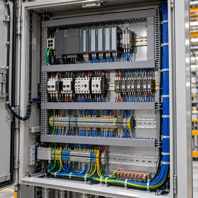
A motor control panel (or motor starter control panel) is a single enclosure, usually wall-mounted or free-standing, built to UL 508A or IEC 61439, that holds starters and controls for a machine or small group of motors. It is the right answer when motors are few and belong to one machine. An MCC is better when motors are many and spread across a plant.
| Factor | Motor control panel | Motor control center |
|---|---|---|
| Motor count | 1 to about 10 | Typically 10 to several hundred |
| Unit replacement | Rewire components in place | Plug-in or withdrawable buckets |
| Expansion | Limited by enclosure | Add units or sections |
| Bus | Small busbar or distribution block | Rated horizontal and vertical bus |
| Location | Near the machine | Central electrical room |
| Standard | UL 508A, IEC 61439 | UL 845, IEC 61439-2 |
Motor control cabinet and electric motor control panel are often used loosely for both. When a machine builder supplies a control panel and the plant supplies an MCC, define where starters live, which side holds the PLC, and how interlocks pass between them. For machine-level panels, see our electrical control panel guide.
Next Steps: Specifying and Sourcing a Motor Control Center
Motor control center cost depends on unit count, starter types (DOL, reversing, star-delta, soft starter, VFD), fixed versus withdrawable construction, short-circuit rating, separation form, intelligent overload relays and communication, arc-resistant design and testing scope. Prices vary by market and date, so compare quotes against the same specification.
An RFQ that MCC suppliers and manufacturers can price consistently includes:
- Motor list with kW or hp, voltage, starter type, and any VFD or soft starter.
- System voltage, frequency, earthing and available fault current.
- Bus ratings, SCCR or Icw, and form of separation.
- Construction standard (UL 845 or IEC 61439-2), wiring class and type or functional unit design.
- Communication protocol and I/O list.
- Enclosure rating, cable entry and spare units or spaces.
- Testing and FAT requirements.
MARS builds GCS and MNS withdrawable low-voltage switchboards configured as motor control centers to IEC 61439-2, with DOL, star-delta, soft-starter and VFD functional units, routine tests on every assembly, FAT welcome and typical lead times of 25 to 45 days. We also supply the distribution transformers that feed them. Review our HV and LV switchgear, then send your motor list via the quote form.
Frequently asked questions
What does MCC stand for in electrical?
MCC stands for motor control center, a floor-standing assembly of vertical sections with a common power bus that houses plug-in or withdrawable units, each containing the starter, short-circuit protection, overload relay and controls for one motor. It centralizes motor control in plants with many motors.
What is an MCC bucket?
An MCC bucket is a removable unit inside a motor control center that holds the equipment for one motor or feeder: disconnect or motor circuit protector, contactor, overload relay, control transformer, pilot devices and terminals. It plugs onto the vertical bus and can be replaced without shutting down the whole MCC.
What is the difference between an MCC and a switchboard?
A switchboard distributes power to feeders through breakers or fused switches. An MCC is mainly for motor control, with starters, overload relays and controls in plug-in units. Both have a main bus and incoming section, but MCCs are built to UL 845 or IEC 61439-2 with motor-specific functional units.
How do you size an MCC bus?
Under NEC 430.24, add 125 percent of the largest motor's full-load current to the full-load currents of all other motors from NEC Table 430.250, plus any non-motor loads. Select the next standard bus rating above that value, add growth margin, and check the short-circuit rating against available fault current.
What is an MCC room?
An MCC room is a dedicated electrical room housing motor control centers and related switchboards, VFDs and PLC panels. It protects equipment from process dust, moisture and heat, controls access, and must provide NEC 110.26 working space, ventilation or cooling, and appropriate arc-flash safety measures.
What is Type 2 coordination in an MCC?
Type 2 coordination, defined in IEC 60947-4-1, means that after a short circuit the starter's contactor and overload relay remain suitable for further use, with only easily separated light contact welding allowed. Type 1 coordination allows damage requiring repair. Type 2 is preferred for critical motors.
Written and reviewed by the MARS application engineering team in Shanghai, who specify and test transformers, switchgear, substations and battery storage for projects in 40+ countries. Last updated .
Tags: motor control center mcc electrical mcc bucket mcc panel motor control center design