Key takeaways
- NFPA 70E requires an arc flash risk assessment before energized work, with review at intervals not exceeding five years or after major system changes.
- IEEE 1584-2018 models three-phase systems from 208 V to 15 kV and five electrode configurations, including VCB, VCBB and HCB.
- The arc flash boundary is the distance at which incident energy falls to 1.2 cal/cm², the onset level for a second-degree burn on bare skin.
- Incident energy is roughly proportional to arcing time, so cutting clearing time from 0.5 s to 0.05 s cuts energy by about ten times.
- NEC 110.16 requires arc flash warning labels on equipment likely to be worked on while energized, with extra data for service equipment of 1,200 A or more.
Quick answer: An arc flash study is an engineering analysis that calculates the incident energy and arc flash boundary at each piece of electrical equipment, using a short-circuit study, protective device coordination and the IEEE 1584 method. NFPA 70E requires an arc flash risk assessment before energized work and a review at least every five years; the study produces equipment labels, PPE requirements and mitigation recommendations.
An arc flash, or electrical flash, is the release of heat, light, pressure and molten metal when current jumps through air between conductors. The energy can exceed 40 cal/cm² at working distance in large low-voltage switchboards, enough to cause fatal burns. The arc flash study is how an employer quantifies that hazard for every panel, switchboard, motor control center and transformer secondary on site.
This article is for facility managers, safety officers and electrical engineers commissioning or updating a study. It explains what arc flash means in engineering terms, the code drivers, how to perform an arc flash study step by step, what a good arc flash analysis report contains, and how equipment design influences the results. For the physics of the event itself, start with our primer on what an arc flash is.
Arc Flash Meaning: What Does an Arc Flash Study Calculate?
An arc flash is an electric arc fault in air that releases thermal energy rapidly enough to burn people at a distance. The definition of arc flash used in NFPA 70E is a hazard associated with the release of energy caused by an electric arc. An arc fault study turns that hazard into numbers.
An arc flash hazard analysis calculates three quantities for each bus or equipment location:
- Arcing current: lower than the bolted fault current because the arc itself has impedance; at 480 V it may be 40–70% of bolted current.
- Incident energy: the thermal energy per unit area at a defined working distance, in cal/cm². Typical IEEE 1584 working distances are 455 mm (18 in) for LV panelboards and MCCs, 610 mm (24 in) for LV switchgear and 910 mm (36 in) for MV switchgear.
- Arc flash boundary: the distance at which incident energy equals 1.2 cal/cm². Anyone inside the boundary needs arc-rated PPE.
These depend on system voltage, bolted fault current, gap between conductors, enclosure size, electrode configuration and, most strongly, the time the upstream protective device takes to clear the arc. That last point is why an arc flash analysis cannot be separated from a protective device coordination study. The terms arc flash assessment, arc flash evaluation, arc flash hazard study and arc flash survey are used loosely in the market; under NFPA 70E the formal term is arc flash risk assessment, of which the engineering calculation is one part.
Is an Arc Flash Study Required by Code?
Arc flash study requirements come from several documents that work together. None of them uses the exact phrase "you must hire an engineer for an arc flash study", but in practice the incident energy method is the only way to satisfy them for most industrial and commercial systems.
| Document | Requirement | Practical effect |
|---|---|---|
| NFPA 70E, Article 130 | Arc flash risk assessment before energized work; determine PPE by incident energy analysis or PPE category tables | Study or table method needed for every task |
| NFPA 70E | Review assessment at intervals not exceeding 5 years and after modifications | Periodic update of the study |
| NEC 110.16(A) | Field-marked warning labels on equipment likely to be examined or serviced energized | Labels on panels, switchboards, MCCs |
| NEC 110.16(B) | Service equipment 1,200 A and above: label with nominal voltage, available fault current, clearing time and date | Requires short-circuit and coordination data |
| NEC 240.87 | Arc energy reduction for breakers rated or adjustable to 1,200 A and above | Maintenance switch, ZSI, differential or similar |
| OSHA 29 CFR 1910.132 and 1910.335 | Employer must assess hazards and provide protective equipment | Enforcement basis in the US |
| CSA Z462 | Canadian equivalent of NFPA 70E | Same approach in Canada |
The NFPA 70E PPE category tables can be used instead of a calculation only when the equipment's fault current and clearing time are within the limits printed in the table notes. Many sites exceed those limits, especially at transformer secondaries, so why do I need an arc flash study? Because without one you usually cannot show that the table method applies, and you cannot produce the NEC 110.16(B) label data.
How to Perform an Arc Flash Study Step by Step
A credible electrical arc flash study follows the same sequence regardless of the software used.
- Define scope. List every location where energized work could occur, typically from the utility point of connection down to 208 V panels, applying the IEEE 1584-2018 guidance on low-energy circuits of 240 V and below.
- Collect field data. Utility available fault current and X/R, transformer kVA and impedance, cable sizes and lengths, protective device types and settings, motor contributions. This is the arc flash survey or audit stage and often takes longer than the analysis.
- Build the model. Create or update the single line diagram and enter it in the analysis software.
- Run the short-circuit study to obtain bolted fault current at each bus. See our fault current calculation guide for the hand method behind it.
- Run the coordination study to confirm device settings and find each upstream clearing time.
- Calculate incident energy using IEEE 1584-2018, with electrode configuration, gap and enclosure dimensions for each equipment type.
- Review results. Flag locations above 8 cal/cm² or 40 cal/cm², and test sensitivity to minimum and maximum utility source cases.
- Recommend mitigation and re-run with proposed settings.
- Issue the report and labels, then train workers on reading them.
A frequent error is calculating only at maximum fault current. Lower fault current can push an inverse-time device into its slower region, so arcing time and incident energy rise. IEEE 1584-2018 also requires a reduced arcing-current case for this reason.
Worked Example: Why Clearing Time Dominates Incident Energy
In IEEE 1584, incident energy at a given location is directly proportional to arcing duration. That gives a simple way to test mitigation options before re-running the full model: E2 = E1 × (t2 / t1).
Consider a 2,000 kVA, 480 V transformer with 5.75% impedance feeding a main switchboard. Full-load current is 2,000,000 / (1.732 × 480) = 2,406 A, and bolted fault current at the secondary with an infinite source is about 2,406 / 0.0575 = 41.8 kA. An arc in the main breaker's line-side compartment is cleared by the transformer primary fuse or relay, not by the LV main breaker, because the fault is upstream of that breaker.
- Suppose the study finds 32 cal/cm² at 455 mm, with the MV primary protection clearing in 0.6 s.
- Adding a light-plus-current arc flash relay that trips the MV breaker gives a total clearing time of about 0.07 s (relay plus 3-cycle MV breaker at 60 Hz).
E2 = 32 × (0.07 / 0.6) = 3.7 cal/cm²
The equipment moves from PPE Category 4 territory to below 4 cal/cm², and the arc flash boundary shrinks substantially. The calculation shows why the most effective mitigation is usually faster protection, not more PPE. Our article on the arc flash relay explains how detection and trip times are achieved, and 480 V incident energy mitigation compares other options.
What Goes in an Arc Flash Analysis Report?
An arc flash study report should allow a different engineer to reproduce the results five years later. Look for these sections.
| Report section | Contents |
|---|---|
| Executive summary | Scope, highest-risk locations, key recommendations |
| Methodology | Standard edition (IEEE 1584-2018), software, assumptions, operating scenarios |
| Data sources | Utility letter, field survey date, nameplate data, assumed values clearly marked |
| Single-line diagram | As-modeled, with bus names matching labels |
| Short-circuit results | Bolted and arcing current at each bus, X/R ratios |
| Coordination curves | Time-current curves with settings and any miscoordination noted |
| Arc flash results table | Bus, voltage, electrode configuration, working distance, clearing device, arcing time, incident energy, boundary |
| Device setting schedule | Recommended relay and trip unit settings |
| Mitigation options | Each with before/after energy |
| Labels | Label format and a copy of each label |
NFPA 70E labels must show nominal voltage, arc flash boundary, and at least one of: available incident energy with working distance, or PPE category, or minimum arc rating of clothing, or site-specific PPE level. Avoid reports that list only PPE categories without the underlying energy values. A good arc flash report also states which equipment exceeded the 40 cal/cm² level, where many safety programs prohibit energized work entirely.
Arc Flash Testing vs Arc Flash Study: Equipment Design Matters
Arc flash testing and the study are often confused. The study calculates exposure for people working on open or energized equipment. Arc flash testing, more correctly internal arc testing, is a laboratory type test proving that closed switchgear contains an internal arc.
- IEC 62271-200 assigns an internal arc classification (IAC) to MV metal-enclosed switchgear, such as IAC AFLR 31.5 kA 1 s, meaning front, lateral and rear accessible sides tested at 31.5 kA for 1 second.
- IEEE C37.20.7 is the North American guide for testing arc-resistant MV and LV switchgear, with accessibility Types 1, 2, 2B and others.
- IEC TR 61641 gives a test method for LV assemblies under internal arcing conditions.
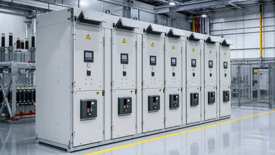
Arc-resistant construction protects people standing in front of closed doors; it does not reduce the incident energy calculated for open-door work, racking or testing. That is why the arc flash program should treat equipment specification and the study together: specify internal-arc-classified switchgear, remote racking, arc flash relays or energy-reducing maintenance switches during design, rather than adding them after the first study reports high values. Our arc flash mitigation solutions guide compares these options by cost and effectiveness.
Building an Arc Flash Program That Stays Current
Arc flash program requirements under NFPA 70E go beyond the calculation. The study is one element of the employer's electrical safety program, which must also include procedures, training, PPE and audits.
- Management of change: any new transformer, utility upgrade, breaker replacement or setting change triggers a review of affected buses.
- Five-year review: even with no known changes, re-verify utility fault data and device settings.
- Maintenance: the study assumes protective devices operate as designed. NFPA 70E links equipment condition to the assessment, and poorly maintained breakers can clear more slowly than modeled. Follow NFPA 70B maintenance practices.
- Training: qualified persons must understand labels, boundaries and PPE selection.
- Hierarchy of controls: elimination by de-energizing first, then engineering controls, then PPE as the last line of defense.
- Audit: field-check a sample of labels and PPE practice each year against the current report.
The best arc flash risk assessment requirements are met when engineering controls are designed in. For new MV switchgear, our substation protection engineering guide covers how relay schemes support fast clearing.
Next Steps: Specifying and Sourcing Lower-Risk Switchgear
MARS does not perform arc flash studies, but our switchgear and transformers are what the study models. Supplying accurate data and choosing equipment that supports fast clearing makes the results lower and the study simpler.
- Request transformer test reports with measured impedance and X/R, not just nameplate values, for the short-circuit model.
- Specify KYN28 metal-clad switchgear with an internal arc classification to IEC 62271-200 and the required IAC sides and duration.
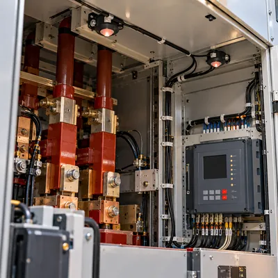
- Ask for arc flash relay provisions (light sensors in busbar, breaker and cable compartments) in MV panels and LV switchboard incomers.
- Specify withdrawable breakers with remote racking capability where operators must rack energized.
- Include required time-current data and relay setting ranges in the submittal package for the coordination study.
When a new transformer or switchboard is added to an existing site, ask the study engineer to model it before the order is placed. Impedance, protection type and clearing time can then be chosen to keep incident energy low rather than corrected afterwards.
Review our HV and LV switchgear range and oil-immersed transformers, then request a quote with your single-line diagram and any study recommendations you need the equipment to meet.
Frequently asked questions
Why do I need an arc flash study?
NFPA 70E requires an arc flash risk assessment before energized work, and NEC 110.16 requires warning labels. For most commercial and industrial systems, only an incident energy study can show the PPE needed and produce label data. It also exposes protection weaknesses that can be fixed before an incident.
How often does an arc flash study need to be updated?
NFPA 70E requires the arc flash risk assessment to be reviewed at intervals not exceeding five years, and whenever major modifications or renovations occur. Utility fault current changes, new transformers, breaker replacements and protective setting changes should each trigger a review of the affected equipment.
What is the difference between an arc flash study and an arc flash assessment?
The study is the engineering calculation of incident energy and boundaries using IEEE 1584. The arc flash risk assessment under NFPA 70E is broader: it uses those results to decide whether a task can be done, which controls and PPE apply, and how likely an arc is, given equipment condition.
What does an arc flash label show?
NFPA 70E labels show nominal voltage, the arc flash boundary, and at least one of incident energy with working distance, PPE category, minimum arc rating of clothing, or site-specific PPE level. NEC service equipment of 1,200 A or more also needs available fault current, clearing time and the label date.
What voltage range does IEEE 1584 cover?
IEEE 1584-2018 covers three-phase AC systems from 208 V to 15 kV. For 208 V to 600 V it applies to bolted fault currents from 500 A to 106 kA, and from 601 V to 15 kV to 200 A to 65 kA. Outside those ranges other methods or conservative assumptions are used.
Is arc flash testing the same as an arc flash study?
No. Arc flash testing usually means internal arc type testing of switchgear to IEC 62271-200 or IEEE C37.20.7, proving that a closed enclosure contains an arc. The study calculates exposure for workers near open or energized equipment. Both matter, but arc-resistant gear does not reduce open-door incident energy.
Written and reviewed by the MARS application engineering team in Shanghai, who specify and test transformers, switchgear, substations and battery storage for projects in 40+ countries. Last updated .
Tags: arc flash study arc flash hazard analysis arc flash assessment arc flash study requirements arc flash analysis report