Key takeaways
- Arc flash relays combine light detection with an overcurrent check, so a camera flash or sunlight alone does not trip the breaker.
- Relay output time with solid-state trip contacts is commonly 1–2 ms, while the breaker adds roughly 30–80 ms to reach full clearing.
- Because incident energy scales with arcing time, cutting clearing from 0.45 s to 0.06 s reduces energy by about 87 percent at the same fault current.
- Point sensors cover individual compartments, while bare fiber-loop sensors run along busbars and detect light anywhere along their length.
- Arc quenching devices go further, creating a deliberate bolted fault within about 5 ms to extinguish the arc before the breaker opens.
Quick answer: An arc flash relay is a protection device that detects the intense light of an arc through optical sensors, usually confirms it with a fast overcurrent check, and trips the upstream breaker within about 1–2 ms of detection. With breaker opening time added, total clearing is typically 35–100 ms, cutting incident energy several-fold compared with time-graded overcurrent protection.
Conventional overcurrent relays are graded in time so that the device nearest a fault trips first. That coordination is essential for selectivity, but it means a busbar fault in a main switchboard may be cleared only after 0.3–1.0 s, long enough for an arc to release dangerous energy and badly damage the equipment. Arc flash detection breaks that trade-off by recognizing the arc itself.
This guide is for protection engineers, switchgear specifiers and maintenance managers. It covers how arc detection works, sensor types, trip logic, a worked calculation of energy reduction, how arc flash protection devices compare with other mitigation methods, and how to commission and maintain the system. If you are still at the stage of quantifying the hazard, read our arc flash study guide first.
What Is an Arc Flash Relay and How Does Arc Detection Work?
An arc flash relay is a dedicated protection relay that trips a circuit breaker when its sensors see the light of an arc, normally supervised by a simultaneous overcurrent signal. It is also called an arc flash protection relay or arc protection device. Its job is to protect people and switchgear by shortening arcing time, not to provide selective overload or fault coordination.
An arc in air emits light of tens of thousands of lux within microseconds, far brighter than normal room lighting. Arc flash detection exploits that: optical sensors inside the enclosure pass light to the relay through fiber or wire, and the relay compares it with a threshold. Because light alone can come from a door opened to bright sunlight or a photographer's flash, most schemes require a second condition: phase or earth current above a set level, measured from existing current transformers. Both conditions must occur within a short window.
The decision is made in hardware logic, not in a slow software scan, so trip output operates in roughly 1–2 ms with semiconductor outputs or 5–10 ms with electromechanical contacts. The relay then opens the breaker feeding the faulted zone. In metal-clad switchgear with a fault in the busbar compartment, that is the incoming breaker or the upstream transformer primary breaker.
Arc detection in this sense is different from the arc-fault circuit interrupter (AFCI) found in homes under UL 1699, which analyzes current waveforms to detect series arcing in branch wiring, and from DC arc-fault detection in PV systems. Those devices protect against fire; the arc flash relay protects against high-energy faults in switchgear.
Arc Flash Sensor Types and Placement
The arc flash sensor is the part of the system that most affects coverage and reliability. Three types are common.
| Sensor type | How it works | Coverage | Best use |
|---|---|---|---|
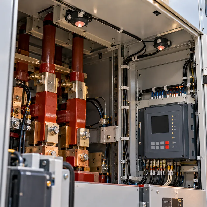
| Point (lens) sensor | Photodiode or lens collecting light in a cone, wired or fiber-connected to the relay | One compartment, typically within a few meters in line of sight | Breaker, cable and busbar compartments of each panel |
| Fiber-loop sensor | Bare optical fiber that admits light along its whole length; both ends at the relay for self-supervision | Continuous along the route, often up to tens of meters | Long busbar runs, LV switchboards with many sections |
| Pressure or combined sensor | Detects pressure rise or both light and pressure | Enclosure-wide | Special cases where light paths are blocked |
Placement rules of thumb
- Cover every compartment where an arc can start: busbar, breaker or truck, and cable termination compartments.
- Install sensors in separate zones so a cable-compartment arc on a feeder trips only that feeder, while a busbar arc trips the incomer.
- Avoid line-of-sight obstruction by barriers and shutters; a sensor behind a metal shutter cannot see an arc on the other side.
- Keep sensors away from openings that admit daylight during maintenance, or rely on current supervision.
- Route fiber with the bend radius specified by the relay supplier and protect it from damage during racking.
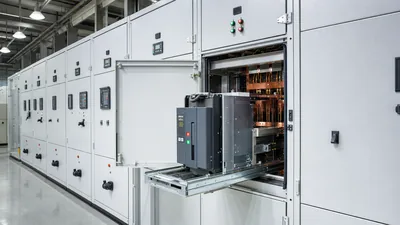
In a KYN28-style panel, a typical arrangement is three point sensors per panel. For the compartment layout behind that, see our metal-clad switchgear engineering guide.
Trip Logic: Light Only, Light Plus Current and Zoning
The trip criteria determine both speed and security. Engineers choose among three main schemes.
- Light only. The relay trips on light alone. It is the fastest and covers faults where current is low, such as high-impedance earth arcs, but it is vulnerable to nuisance tripping from external light. It is usually reserved for compartments that are never opened while energized.
- Light plus overcurrent. Light must coincide with current above a threshold, typically set above maximum load but below minimum arcing current. This is the most common scheme. The current element is non-directional and instantaneous, so it adds only a millisecond or two.
- Light plus current with zone selectivity. Each sensor is assigned to a zone, and each zone has its own trip output. A feeder cable-compartment arc trips the feeder breaker; a busbar arc trips the incomer; an arc in the incomer's own line-side compartment trips the upstream breaker. Larger systems use multiple units linked by fiber to share light and current signals.
Breaker failure logic is important: if the selected breaker does not interrupt within a set time, often 100–150 ms, the relay should trip the next upstream device. Setting the current threshold also needs care. With IEEE 1584 arcing current at 480 V possibly as low as half the bolted fault current, the threshold must stay below the reduced arcing current case, not merely below the bolted fault value. Coordinate the setting with the protection relay settings already applied for overcurrent grading.
Worked Example: Incident Energy Reduction with Arc Flash Detection
Consider an 11 kV metal-clad switchboard fed from a 20 MVA transformer. The busbar is protected by the transformer LV-side incomer relay, graded above the outgoing feeders with a definite-time delay of 0.40 s. The incomer vacuum circuit breaker opens in 50 ms.
- Conventional total clearing time:
t1 = 0.40 + 0.05 = 0.45 s - Arc flash relay: detection and output 2 ms, current check 1 ms, breaker 50 ms, plus a 5 ms allowance:
t2 ≈ 0.058 s
For the same arcing current and enclosure, IEEE 1584 incident energy scales linearly with time: E2 = E1 × (t2 / t1). If the study gives E1 = 14 cal/cm² at 910 mm, then E2 = 14 × 0.058 / 0.45 = 1.8 cal/cm², an 87% reduction.
Damage scales similarly. Arc energy delivered into the enclosure is roughly W = V_arc × I_arc × t. With an arc voltage of several hundred volts per phase and an arcing current of 20 kA, every 100 ms of arcing adds megajoules of energy, which is why fast detection often turns a destroyed panel into a cleaned and repaired one.
Two cautions apply. First, the reduced energy is valid only if the arc flash relay is in service and tested; the study and label should state that assumption. Second, an arc in the compartment upstream of the tripped breaker is not cleared by that breaker; the scheme must trip the next device upstream. Our medium voltage breaker guide covers breaker opening times that feed into t2.
Arc Flash Protection Devices Compared
An arc flash relay is one of several arc flash protection devices and schemes. They differ in speed, cost and selectivity.
| Method | Typical clearing time | Selectivity | Notes |
|---|---|---|---|
| Arc flash relay (light + current) | 35–100 ms including breaker | By zone | Retrofit possible; sensors must see the arc |
| Arc quenching device with relay | Arc extinguished in about 2–5 ms; breaker clears later | Bus-wide | Creates a controlled bolted fault; equipment must withstand it |
| Bus differential (87B) | Relay about 1–2 cycles plus breaker | Exact zone | Needs dedicated CTs; detects faults, not only arcs |
| Zone-selective interlocking | Short-time pickup with minimum delay, often 50–100 ms plus breaker | Good | Uses communication between trip units |
| Energy-reducing maintenance switch | Instantaneous while enabled | Lost while enabled | Satisfies NEC 240.87; depends on operator action |
| Current-limiting fuses | Under half a cycle in current-limiting range | Good with ratio tables | Effective only above threshold current |
Many designs combine methods: bus differential or arc flash relays in MV switchgear, zone-selective interlocking in LV switchboards, and a maintenance switch for work on downstream panels. For a broader cost and effectiveness comparison, see our arc flash mitigation solutions guide; for the physics, our explainer on what arc flash is.
Arc Flash Monitoring, Self-Supervision and Testing
An arc flash relay is silent for years and then must work in milliseconds, so continuous self-checking and periodic testing are essential.
Arc flash monitoring features to require
- Sensor supervision: fiber loops checked by sending test light through the loop; point sensors checked for open or short circuit.
- Trip circuit supervision of the breaker coil wiring.
- Event recording with which sensor saw light, current magnitude and trip time.
- Alarm outputs to SCADA for sensor failure or relay internal faults.
Arc flash monitoring is sometimes confused with continuous thermal or partial discharge monitoring, which detect developing problems before they become arcs. They complement each other; see our partial discharge testing guide.
Commissioning steps
- Verify sensor locations and zone assignment against the drawings.
- Expose each sensor to a high-intensity test light source and confirm the correct zone indication.
- Inject secondary current to confirm the overcurrent threshold.
- Test combined light plus current and measure relay output time with a timer.
- Trip each assigned breaker, preferably at least once with primary circuits de-energized, and confirm breaker failure backup logic.
- Record settings and results, and include them in the arc flash study assumptions.
Repeat functional tests at the interval recommended by the relay supplier and the site's maintenance program, typically aligned with breaker maintenance.
Next Steps: Specifying and Sourcing Switchgear with Arc Protection
Arc flash relays are most effective when designed into the switchgear from the start, with sensor mounting points, fiber routing and CT inputs included in the factory build. When you order MARS KYN28 metal-clad switchgear or IEC 61439 LV switchboards, state the arc protection requirements in the RFQ so they are engineered into the panels and covered by the factory tests.
In your RFQ, state:
- Required internal arc classification to IEC 62271-200 (for example IAC AFLR 25 kA 1 s) for MV panels.
- Arc flash relay scheme: light only or light plus current, number of zones, and which breakers each zone trips.
- Sensor type and quantity per panel and compartment.
- CT ratios and secondary values for the current check.
- Communication protocol and alarm outputs required by the SCADA system.
- Factory test requirements, including a light-injection functional test at FAT.
Ask for the sensor layout drawing and zone trip matrix as part of the submittal, so the protection engineer can approve them before panels are built. Browse our HV and LV switchgear and request a quote with your single-line diagram and arc flash study recommendations. Typical switchgear lead time is 25–45 days.
Frequently asked questions
How fast does an arc flash relay trip?
The relay itself typically issues a trip in about 1–2 ms with solid-state outputs, or 5–10 ms with electromechanical contacts. Total clearing time adds the breaker opening time, usually 30–80 ms for vacuum and air circuit breakers, giving roughly 35–100 ms overall.
Why do arc flash relays use both light and current?
Light alone can be produced by sunlight through an open door, welding or a camera flash. Requiring simultaneous overcurrent confirms a real fault and prevents nuisance trips. The current element is instantaneous, so it adds only about a millisecond to operating time.
Where should arc flash sensors be installed?
Install sensors in every compartment where an arc can start: busbar, breaker and cable compartments of each panel. Assign them to zones so each zone trips the breaker feeding it. Fiber-loop sensors suit long busbars, while point sensors suit individual compartments.
Can an arc flash relay be retrofitted to existing switchgear?
Yes, in most cases. Sensors are mounted inside existing compartments, fiber or wiring is routed to a relay in the low-voltage compartment, and the trip output is wired to the breaker. Check line of sight around barriers, CT availability for the current check and the arc flash study update.
Does an arc flash relay reduce the PPE category?
It can, because incident energy is proportional to arcing time. The arc flash study must be re-run with the shorter clearing time, and the labels must state that the reduced value applies only when the relay is in service. Many sites keep higher PPE when the system is bypassed.
What is the difference between an arc flash relay and an AFCI breaker?
An AFCI breaker, listed to UL 1699, protects residential branch circuits from fire by recognizing arcing patterns in current. An arc flash relay protects switchgear and workers from high-energy arc faults by detecting light and overcurrent, then tripping an upstream breaker very quickly.
Written and reviewed by the MARS application engineering team in Shanghai, who specify and test transformers, switchgear, substations and battery storage for projects in 40+ countries. Last updated .
Tags: arc flash relay arc flash detection arc detection arc protection device arc flash sensor