Key takeaways
- IEC 60270 defines conventional partial discharge measurement, expressing PD magnitude as apparent charge in picocoulombs after calibration with a known charge.
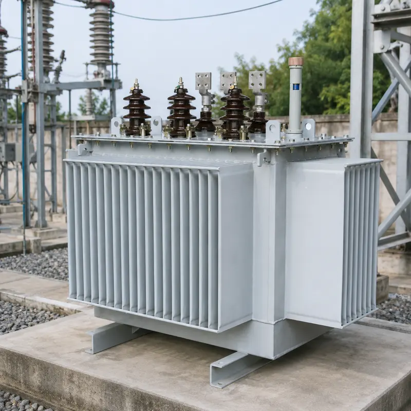
- Cast-resin dry-type transformers to IEC 60076-11 are routine PD tested, with a common limit of 10 pC at 1.3 times rated voltage after pre-stress.
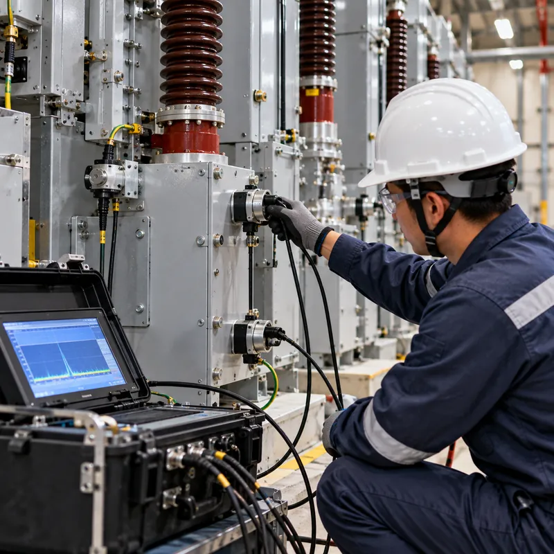
- Transient earth voltage sensors detect PD inside metal-clad switchgear from the outside, while airborne ultrasonic sensors near 40 kHz detect surface discharge and corona.
- HFCT sensors clamped on cable earth straps detect cable partial discharge, and IEEE 400.3 guides PD testing of shielded power cables in the field.
- Rising partial discharge trends matter more than single readings, so permanent partial discharge monitoring systems record magnitude, repetition rate and phase pattern.
Quick answer: Partial discharge testing detects small electrical discharges that bridge only part of an insulation system, such as a void in epoxy or a sharp edge in air. Offline tests apply voltage and measure apparent charge in picocoulombs to IEC 60270; online methods such as TEV, ultrasonic, HFCT and UHF sensors find PD in energized switchgear, cables and transformers before insulation fails.
Most medium and high-voltage insulation failures do not happen suddenly. They start with partial discharge: tiny sparks inside a void, along a contaminated surface or around a sharp conductor edge, repeated thousands of times per second. Over months or years the discharges erode insulation until it breaks down. Detecting PD early is one of the most effective condition assessment tools available for switchgear, cables and transformers.
This guide is for test engineers, asset managers and buyers of MV equipment. It explains what partial discharge is and its types, how partial discharge testing works offline and online, sensors and partial discharge test equipment, acceptance limits in key standards, a worked test example and how to set up partial discharge monitoring. It complements our broader insulation testing procedures and standards guide.
What Is Partial Discharge?
Partial discharge (PD) is a localized electrical discharge that only partially bridges the insulation between conductors, occurring where the local electric field exceeds the breakdown strength of a small region such as a gas-filled void. IEC 60270 uses this definition. The discharge does not short the electrodes, so the equipment keeps working, but each event releases energy that damages the surrounding material.
Why voids discharge: in a void inside solid insulation, the field is enhanced because the gas has lower permittivity than the surrounding material. With epoxy at a relative permittivity of about 4, the field in a flat void can be up to roughly four times the field in the solid, while the gas breaks down at a far lower stress than the solid. Discharge then repeats each half cycle once the voltage exceeds the inception level.
Two voltage levels describe PD behavior:
- Partial discharge inception voltage (PDIV): the lowest applied voltage at which PD above a set threshold appears when voltage is raised.
- Partial discharge extinction voltage (PDEV): the voltage at which PD stops when voltage is lowered, usually lower than PDIV.
A healthy design keeps both comfortably above the maximum operating voltage, so PD does not occur in service. Partial discharge voltage tests therefore use test voltages above operating voltage. PD also produces measurable side effects: current pulses, electromagnetic radiation, acoustic emission, light, heat and chemical byproducts such as ozone, nitric acid deposits in air, or hydrogen in transformer oil, which is why DGA oil testing can indicate PD in oil-filled transformers.
Types of Partial Discharge
The types of partial discharge differ in location, cause and risk. Identifying the type is as important as measuring magnitude.
| Type | Where it occurs | Typical cause | Risk |
|---|---|---|---|
| Internal (void) discharge | Gas voids or delamination inside solid insulation | Casting defects, poor impregnation, thermal cycling | High; erodes insulation and leads to treeing |
| Surface discharge (tracking) | Along insulator surfaces, cable terminations, bushings | Contamination, moisture, poor stress control | High in switchgear; forms carbon tracks |
| Corona | Around sharp points or edges in gas or air | Sharp conductors, protruding bolts, broken strands | Usually lower in open air, but produces ozone and corrosive deposits |
| Electrical treeing | Branching channels growing in solid insulation | Long-term void discharge or contaminants | Very high; often precedes breakdown |
| Floating potential discharge | Between a floating metal part and nearby conductor | Loose shields, unbonded components | Variable; large pulses, mechanical damage |
Corona partial discharge is often seen on overhead lines and outdoor substations. In enclosed MV switchgear, any corona indicates a defect, because designs control stress internally. Surface discharge at cable terminations is one of the most common findings in field surveys of switchgear rooms, especially where humidity and condensation are poorly controlled.
Phase-resolved PD (PRPD) patterns, which plot discharge magnitude against the phase angle of the applied voltage, help distinguish these types. Void discharges cluster in the rising quarters of both half cycles, while corona appears mainly near one voltage peak.
How Does Partial Discharge Testing Work?
Partial discharge detection uses either the conventional electrical method or one of several unconventional methods that sense other effects of PD.
Conventional method to IEC 60270
The test object is energized from a PD-free high-voltage source. A coupling capacitor provides a low-impedance path for the fast current pulses produced by PD, and a measuring impedance converts them into voltage signals for the PD instrument. The instrument integrates the pulses within a defined bandwidth to give apparent charge, in pC. This is not the actual charge in the void, which cannot be measured directly, but the charge that, injected at the terminals, would produce the same reading.
Calibration is mandatory before each test: a calibrator injects a known charge q0 = U0 × C0 at the terminals. For a 10 V step through a 10 pF capacitor, q0 = 10 × 10 pF = 100 pC. The scale factor is set so the instrument reads 100 pC, then the calibrator is removed and voltage is applied. Background noise must be measured and kept well below the acceptance limit, typically under half of it.
Unconventional methods
These detect electromagnetic, acoustic or radio-frequency emissions and are widely used for online partial discharge testing because they do not need a separate HV supply or disconnection. They are generally not calibrated in pC, so they are used for trending and location rather than pass/fail acceptance. IEC TS 62478 covers electromagnetic and acoustic PD measurement methods.
Partial Discharge Sensors and Test Equipment
Partial discharge test equipment ranges from handheld survey tools to laboratory systems. Choose sensors according to the asset and whether it is energized.
| Method | Sensor | Frequency range | Best for | Online? |
|---|---|---|---|---|
| Conventional IEC 60270 | Coupling capacitor and measuring impedance | Tens to hundreds of kHz | Factory acceptance, routine tests | No |
| Transient earth voltage (TEV) | Capacitive probe on metal enclosure | About 3–100 MHz | Internal PD in metal-clad switchgear | Yes |
| Airborne ultrasonic | Ultrasonic microphone at panel gaps or vents | Around 40 kHz | Surface discharge, corona | Yes |
| High-frequency current transformer (HFCT) | Split-core CT on cable earth straps | About 100 kHz–30 MHz | Cables, terminations, joints | Yes |
| Ultra-high frequency (UHF) | Internal or window antennas | About 300 MHz–3 GHz | GIS, large transformers | Yes |
| Acoustic emission | Piezoelectric sensors on transformer tank | Around 20–300 kHz | Locating PD in oil-filled transformers | Yes |
A handheld partial discharge detector combining TEV and ultrasonic is the standard tool for routine switchgear surveys. Readings are compared with background levels measured on nearby metalwork away from the switchgear, and with previous surveys. Widely used rules of thumb treat TEV readings within a few dB of background as normal and readings rising above about 20–30 dBmV as requiring investigation, but each instrument supplier publishes its own interpretation bands, so use consistent equipment for trending.
Partial discharge measurement equipment for cables usually adds a time-domain reflectometry function to locate a PD source along the cable from the arrival times of direct and reflected pulses.
PD Test of Transformers, Switchgear and Cables: Acceptance Limits
Factory PD tests are part of routine or type testing for many MV and HV products. Typical criteria, which you should always confirm against the edition named in the contract, are:
| Equipment | Standard | Typical test and limit |
|---|---|---|
| Cast-resin dry-type transformer | IEC 60076-11 | Routine: pre-stress at 1.8 Ur, then ≤ 10 pC at 1.3 Ur |
| Oil-immersed power transformer | IEC 60076-3 | Induced voltage test with PD measurement; for example ≤ 100 pC at 1.2 Ur/√3 and ≤ 250 pC at 1.58 Ur/√3 (2013 edition) |
| Extruded MV cable | IEC 60502-2 | Routine: no discharge above 10 pC at 1.73 U0 |
| Instrument transformers | IEC 61869 series | Routine PD at specified fractions of Um, limits typically in the 5–50 pC range by insulation type |
| Cast epoxy switchgear components | Component specifications per IEC 60270 method | Limits set by supplier and buyer, often single-digit pC |
Worked example: PD test on a 10 kV dry-type transformer
A cast-resin transformer has rated HV winding voltage Ur = 10 kV. Under IEC 60076-11, the induced test is applied from the LV side:
- Calibrate the PD circuit with a known charge, for example 50 pC, and verify background noise below 5 pC.
- Raise to pre-stress voltage
1.8 × Ur = 18 kVfor 30 s. - Reduce to measurement voltage
1.3 × Ur = 13 kVand hold for 3 min. - Record PD; the unit passes if PD is ≤ 10 pC throughout.
A transformer that shows 50 pC at 13 kV may still operate for years, but it indicates a casting void that will grow, which is exactly what the test is designed to reject. See our transformer factory acceptance testing checklist for where PD fits in FAT.
Online Partial Discharge Testing and Cable PD in the Field
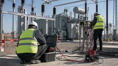
Online partial discharge testing assesses equipment in service, without an outage, under real temperature and voltage conditions. It is the main condition assessment tool for switchgear fleets and cable networks.
Switchgear surveys
A typical survey of a switchboard room takes TEV readings on each panel front and rear, ultrasonic readings at door seams and vents, and HFCT readings on cable earth straps. Panels with elevated readings are checked with a second method to separate internal PD from external noise.
Cable partial discharge testing
For cables, two approaches are common:
- Online HFCT testing at terminations while the cable is in service, with pulse arrival analysis to locate sources.
- Offline testing with a very-low-frequency (VLF, typically 0.1 Hz) source to IEEE 400.2 or a damped AC source, with PD measured to IEEE 400.3. The cable is energized to a defined multiple of U0, PDIV is recorded, and PD sources are mapped along the length.
Offline tests give calibrated pC values and can raise voltage above service levels to expose weaker defects; online tests give trend data with no outage. Many owners use online surveys to prioritize and offline tests to confirm. Field PD results should be interpreted together with insulation resistance and tan delta results described in our power factor test guide.
Partial Discharge Monitoring Systems for Switchgear and Transformers
A partial discharge monitoring system is a permanently installed set of sensors and a data unit that measures PD continuously and alarms when levels or trends exceed set thresholds. It is used where periodic surveys are not frequent enough, such as critical feeders, aging switchgear or large transformers.
Setting up a partial discharge monitoring system for switchgear typically involves these steps:
- Select assets by criticality and condition history.
- Choose sensors: TEV and HFCT for metal-clad switchgear and cable terminations; UHF for GIS; UHF or acoustic plus DGA for transformers.
- Install sensors during an outage where internal mounting is required, and record sensor positions.
- Establish baselines over several weeks, capturing load and humidity variation.
- Set alarms on magnitude, pulse count rate and rate of change, not just absolute level.
- Integrate with SCADA or an asset management platform, ideally via IEC 61850 or Modbus.
- Review patterns regularly and confirm alarms with an offline or handheld test before intrusive work.
Monitoring and fast arc protection serve different purposes: PD monitoring warns weeks or months ahead, while an arc flash relay limits damage in milliseconds once a fault occurs. Monitoring data also feeds into the digital asset models discussed in our digital substation guide.
Next Steps: Specifying PD Performance When Sourcing Equipment
The cheapest place to control partial discharge is in the factory. MARS carries out routine tests on every unit; for cast-resin dry-type transformers this includes the IEC 60076-11 partial discharge measurement, and FAT can be witnessed.
In your RFQ, specify:
- PD acceptance limits and test voltages for each product: transformers, switchgear components, instrument transformers.
- Whether PD tests are required as routine (every unit) or type (one unit), and witness requirements.
- Background noise limits and calibration records in test reports.
- Provisions for online monitoring: TEV sensor positions, HFCT access on cable earths, or UHF sensor ports.
- Environmental design: anti-condensation heaters, humidity control and creepage distances for the site's pollution level.
Ask for PD results in the routine test report with the calibration value, background noise and test voltages recorded, so later field measurements can be compared against a factory baseline. Browse our HV and LV switchgear and dry-type transformers, and request a quote with your PD test requirements. For voltage class context, see our guide to LV, MV, HV and EHV voltage ranges.
Frequently asked questions
What is a PD test?
A PD test measures partial discharges in electrical insulation by applying voltage and detecting the small current pulses, radio emissions or sound they produce. Factory PD tests to IEC 60270 report apparent charge in picocoulombs against a limit. Field PD tests use sensors such as TEV, HFCT and ultrasonic to assess energized equipment.
What is an acceptable partial discharge level?
It depends on the equipment and standard. Cast-resin transformers to IEC 60076-11 commonly require 10 pC or less at 1.3 times rated voltage, and extruded MV cables to IEC 60502-2 no more than 10 pC at 1.73 U0. Oil-immersed power transformers have limits of a few hundred pC in the induced voltage test.
How does partial discharge testing work on a transformer?
The transformer is energized through an induced voltage test, usually from the LV side, while a coupling capacitor and PD instrument measure apparent charge at the HV terminals. The circuit is first calibrated with a known charge. Voltage is raised to a pre-stress level, then held at a measurement level while PD is recorded.
Can partial discharge be detected while equipment is energized?
Yes. Online methods such as transient earth voltage probes, airborne ultrasonic sensors, high-frequency current transformers on cable earths and UHF antennas detect PD in service without an outage. They are best for trending and locating sources, while calibrated offline tests give pass or fail values.
What causes partial discharge in switchgear?
Common causes are voids in cast epoxy insulators, contaminated or damp insulation surfaces, poorly made cable terminations, sharp edges or loose hardware, and floating metal parts. Condensation from inadequate heating or ventilation is a frequent contributor to surface discharge in MV switchrooms.
Is corona the same as partial discharge?
Corona is one type of partial discharge. It occurs in gas or air around sharp points or edges where the local field ionizes the gas. Other types include internal void discharge, surface discharge and electrical treeing. Corona in enclosed MV switchgear indicates a defect, while some corona on overhead lines is expected.
Written and reviewed by the MARS application engineering team in Shanghai, who specify and test transformers, switchgear, substations and battery storage for projects in 40+ countries. Last updated .
Tags: partial discharge testing partial discharge pd test partial discharge monitoring partial discharge detection