Key takeaways
- Industrial control panels in the US are commonly built to UL 508A and installed under NEC Article 409, which requires a marked short-circuit current rating.
- NFPA 79 and IEC 60204-1 set wiring colors for machinery, such as red for AC control, blue for DC control and green-yellow for protective earth.
- Panel SCCR is limited by the weakest power-circuit component unless a current-limiting device upstream is documented under UL 508A Supplement SB.
- A sealed painted steel enclosure dissipates roughly 5.5 W per square meter per kelvin, so 180 W of losses in 2.4 m² raises internal temperature about 14 K.
- A complete drawing set includes power schematic, control ladder or PLC I/O schematic, panel layout, terminal schedule and bill of materials.
Quick answer: An electrical control panel is an enclosure that houses the devices controlling a machine or process: PLC, power supplies, contactors, overload relays, terminals and HMI. It is built from a set of drawings (power schematic, PLC I/O wiring schematic and panel layout) and, in the US, is typically listed to UL 508A with a marked short-circuit current rating (SCCR).
Control panels sit between the power system and the process: the switchboard delivers energy, and the control panel decides when motors start, valves open and alarms sound. A panel that is poorly documented, undersized for heat or mislabeled for short-circuit rating is one of the most common reasons for failed inspections and commissioning delays.
This guide is written for engineers, plant maintenance teams and buyers who specify, review or source control panels. It covers what goes inside, how to read and produce a simple electrical wiring diagram and PLC wiring schematic, the SCCR and thermal checks that inspectors look for, and how to evaluate electrical panel manufacturers and suppliers.
What Is an Electrical Control Panel?
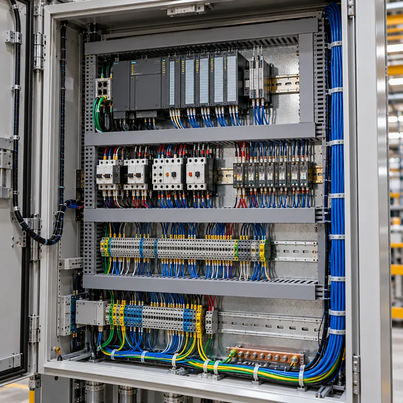
An electrical control panel is an assembly of control and power devices mounted on a back plate inside an enclosure, wired to operate and protect equipment according to a defined logic. It differs from a distribution panel or panelboard, which mainly divides power among branch circuits, and from a switchboard, which handles bulk power at the building level. A control panel may contain small power circuits, such as motor feeders, but its purpose is control.
Typical contents are:
- Incoming disconnect and branch protection (MCBs, fuses or MCCBs).
- Control power: a control transformer for 120 V or 230 V AC and a 24 V DC power supply.
- PLC or safety controller with digital and analog I/O modules.
- Motor control: contactors, overload relays, soft starters or variable frequency drives.
- Interposing relays, timers and safety relays.
- Terminal blocks, wire duct, DIN rail and grounding bar.
- Operator devices: HMI, pushbuttons, selector switches and pilot lights on the door.
Panels for machinery follow NFPA 79 in North America or IEC 60204-1 elsewhere; general low-voltage assemblies follow IEC 61439-1 and -2. When a control panel grows to include many motor feeders in withdrawable units, it starts to look like a motor control center, which is designed and tested as switchgear rather than as a control panel.
How to Read a Panel Diagram and Wiring Control Diagram
A control panel is defined by a drawing set, not a single diagram. Each drawing answers a different question.
| Drawing | What it shows | Who uses it |
|---|---|---|
| Single-line or power schematic | Incoming supply, disconnect, branch protection, motor feeders | Designer, inspector |
| Control ladder diagram | Relay logic between two control rails, one rung per function | Electrician, troubleshooter |
| PLC I/O wiring schematic | Each field device wired to a PLC terminal and address | Builder, programmer, commissioning |
| Panel layout drawing | Physical position of devices on back plate and door, dimensions | Builder, buyer |
| Terminal and cable schedule | Terminal numbers, wire numbers, field cable cores | Installer |
| Panel board schedule | Circuit numbers, breaker sizes, loads per circuit | Electrician, facility owner |
A simple electrical wiring diagram for a motor starter, for example, shows L1-L2-L3 through a breaker and contactor to the motor, while the control circuit below shows a stop button (normally closed) in series with a start button (normally open) and a seal-in contact from the contactor in parallel with the start button. That three-wire control rung is the foundation of most wiring control diagrams. Symbols follow IEC 60617 or the NFPA 79/IEEE 315 conventions; our motor control symbols reference and the general electrical wiring diagram guide cover both. A good panel board schematic diagram also uses cross-references, so each coil points to the sheet and column of its contacts.
PLC Wiring Schematic: Inputs, Outputs and Power
A PLC wiring schematic is the drawing that shows how every field sensor and actuator connects to a specific PLC input or output terminal, including its power source and common. It is the drawing most used during commissioning, so its accuracy matters more than its appearance.
Sinking and sourcing
For 24 V DC digital inputs, a sourcing (PNP) sensor switches +24 V to the input, so the input module must be sinking, with its common tied to 0 V. A sinking (NPN) sensor switches 0 V, so the module must be sourcing, with its common at +24 V. Mixing the two without checking is a frequent cause of inputs that never turn on. Outputs follow the same logic: relay outputs can switch AC or DC; transistor outputs are DC only and must match the load polarity.
What a good PLC schematic drawing includes
- One sheet per I/O module, showing each channel, its address (for example I0.3 or %IX0.3) and the device tag.
- Fuse or electronic circuit protection for each 24 V group.
- Field terminal numbers between the PLC and the device, so the installer can wire to terminals rather than to the module.
- Analog signals with shield termination, loop power source (2-wire or 4-wire transmitter) and signal range such as 4–20 mA.
- Safety circuits drawn separately, showing dual-channel wiring to the safety relay or safety PLC.
Wire color helps maintenance. NFPA 79 recommends red for ungrounded AC control conductors, blue for ungrounded DC control, white or gray for grounded conductors, orange for circuits that stay live with the main disconnect off, and green or green-yellow for equipment grounding. IEC 60204-1 uses similar conventions with light blue for neutral.
SCCR: How Is a Control Panel's Short-Circuit Rating Determined?
NEC 409.110 requires industrial control panels to be marked with their short-circuit current rating, and NEC 409.22 requires that rating to be at least the available fault current where the panel is installed. UL 508A Supplement SB provides the method.
- List every power-circuit component: disconnect, branch protection, contactors, overloads, drives, terminal blocks and power distribution blocks.
- Record each component's SCCR from its marking or the UL 508A default table. Unmarked components such as contactors often default to 5 kA.
- Apply tested combination ratings where a contactor and overload are listed with a specific breaker or fuse at a higher value.
- Apply current-limiting devices: a listed current-limiting fuse or breaker on the feeder can raise the rating of downstream branch components if its let-through is below their ratings.
- Take the lowest value as the panel SCCR and confirm it is not below the available fault current.
Example: a panel has a 65 kA disconnect, Class J branch fuses with 100 kA interrupting rating, and contactor-overload combinations listed at 65 kA with Class J fuses, but one unmarked power distribution block rated 10 kA. The panel SCCR is 10 kA until the block is replaced with one rated 65 kA or protected by a current-limiting device. If the site has 35 kA available, the panel fails. You find that available current with a fault current calculation at the panel's supply point.
Thermal Design: Will the Panel Overheat?
Drives, power supplies and contactor coils all produce heat, and electronics typically need internal air at or below 40–50 °C. A quick heat balance tells you whether a sealed enclosure is enough or whether you need filter fans or an air conditioner.
The basic formula for a sealed enclosure is ΔT = P / (k × A), where P is the internal heat loss in watts, k is the heat transfer coefficient (about 5.5 W/m²·K for painted sheet steel in still air) and A is the effective exposed surface area in m², calculated per IEC/TR 60890 rules that discount sides against walls.
Worked example. A 800 × 1,200 × 300 mm wall-mounted steel panel holds a 7.5 kW drive losing 150 W, a 24 V power supply losing 15 W and PLC plus relays losing 15 W, for P = 180 W. With its back against a wall, the effective area is about 2.4 m².
ΔT = 180 / (5.5 × 2.4) = 13.6 K- At 40 °C ambient, internal air reaches about 53.6 °C, above a 50 °C limit.
The fix is forced ventilation sized by V = 3.1 × P_excess / ΔT_allowed (m³/h, at sea level). Allowing a 10 K rise means the enclosure can passively shed 5.5 × 2.4 × 10 = 132 W, leaving 48 W excess. Required airflow is 3.1 × 48 / 10 ≈ 15 m³/h; choose a filter fan of about 30 m³/h free-blowing to allow for filter loss. If ambient air is dusty or wet, which also affects your choice under the NEMA enclosure ratings, use a closed-loop air conditioner instead.
Electrical Panel Manufacturers: How to Evaluate Suppliers
Searches for electrical panel manufacturers, panel manufacturers in the USA or an electrical control panel company usually come from buyers who need a reliable builder for repeat machines or a one-off process skid. The capabilities that matter are similar wherever the shop is located.
| Criterion | What to ask for | Why it matters |
|---|---|---|
| Certification | UL 508A shop listing for US projects; IEC 61439 design verification for IEC markets | Inspectors require the listing mark or verification records |
| Engineering | Drawings in your format, wire numbering, revision control | Errors in drawings become errors in wiring |
| Test procedure | Point-to-point check, insulation test, functional I/O test, FAT | Catches faults before shipment |
| Component sourcing | Approved vendor list, local spares availability | Lifecycle support in the field |
| SCCR documentation | Supplement SB calculation sheet | Proves the marked rating |
| Quality system | ISO 9001, traceable inspection records | Consistency across batches |
Power panel manufacturers that build distribution boards and motor control centers usually also need IEC 61439 type-tested busbar systems; our overview of IEC 61439 explains design verification. Ask any supplier for a sample drawing set and a recent FAT report before placing an order.
Control Panel Build and Test Checklist
Whether you build in-house or audit an outside electrical panel supplier, the following sequence catches most problems before the panel leaves the shop.
- Freeze the drawings: power schematic, control and PLC schematic, layout and BOM at a released revision.
- Inspect incoming components against the BOM, including voltage ratings of coils and SCCR markings.
- Mount and wire using ferrules, wire markers at both ends, segregated power and signal ducts, and torque marks on power terminals.
- Point-to-point check every wire against the schematic before power is applied.
- Insulation resistance test on power circuits with electronics disconnected; see our guide to checking insulation resistance.
- Power up control circuits only, verify 24 V polarity and fuse ratings.
- Functional I/O test: force each input and output and confirm the HMI and PLC addresses match the schematic.
- Label and document: nameplate with voltage, full-load current and SCCR; as-built drawings in the door pocket.
Keep the signed test sheet with the as-built drawings; it is the first document an inspector or service engineer will ask for. A clean layout also helps later readers; our guide to reading electrical drawings explains the conventions technicians expect.
Next Steps: Specifying and Sourcing Control and Power Panels
MARS manufactures the power distribution side of an installation, not stand-alone PLC control panels. Our IEC 61439 low-voltage switchboards (GGD fixed type, GCS and MNS withdrawable types) feed control panels and can include motor feeder functional units in MNS and GCS sections, while upstream we supply KYN28 metal-clad switchgear, ring main units and distribution transformers. For high-current links between transformer and board, see our bus duct guide.
For any panel RFQ, whether to us for distribution boards or to a control panel builder, include:
- Single-line diagram with supply voltage, frequency and available fault current.
- Required SCCR or Icw and the standard set (UL 508A, NFPA 79, IEC 60204-1 or IEC 61439).
- Load list with motor ratings, starting method and any drives.
- Enclosure type and IP or NEMA rating, ambient temperature and altitude.
- Drawing format, wire color and numbering conventions, and FAT requirements.
Agree in advance who owns the interface between the switchboard feeder and the control panel incomer, including cable sizing, protection settings and the SCCR available at the panel terminals. Explore our HV and LV switchgear and send your single-line diagram for a quote. Typical lead time for switchgear is 25–45 days.
Frequently asked questions
What is the difference between a control panel and an electrical panel?
An electrical panel or panelboard distributes power to branch circuits through breakers. A control panel contains devices that control equipment, such as PLCs, contactors, relays and drives. Control panels may include small power circuits for motors, but their main job is logic and protection of a machine or process.
What standard applies to industrial control panels in the US?
Industrial control panels are generally built and listed to UL 508A and installed under NEC Article 409, which requires a marked short-circuit current rating. Panels that are part of industrial machinery must also follow NFPA 79 for wiring practices, conductor colors and disconnecting means.
How do you draw a simple PLC wiring schematic?
Draw one sheet per I/O module. Show the 24 V DC supply and its protection, each channel with its PLC address and device tag, the field terminal number, and the device symbol. Indicate sinking or sourcing commons and analog loop power. Keep safety circuits on separate sheets.
How is control panel SCCR calculated?
Under UL 508A Supplement SB, list the short-circuit rating of every power-circuit component, apply any tested combination ratings or current-limiting devices, and take the lowest resulting value as the panel SCCR. The marked SCCR must equal or exceed the available fault current at the installation.
What size fan does a control panel need?
First calculate the heat the enclosure can shed passively, k × A × ΔT, using about 5.5 W/m²·K for painted steel. Subtract it from total internal losses. Airflow in m³/h is about 3.1 times the excess watts divided by the allowed temperature rise in kelvin, then add margin for filter losses.
What should I ask an electrical panel manufacturer before ordering?
Ask for their UL 508A listing or IEC 61439 verification records, a sample drawing set, their factory test procedure, SCCR calculation method, component sourcing policy and quality certification such as ISO 9001. A recent factory acceptance test report shows how they actually test.
Written and reviewed by the MARS application engineering team in Shanghai, who specify and test transformers, switchgear, substations and battery storage for projects in 40+ countries. Last updated .
Tags: electrical control panel plc wiring schematic panel board diagram electrical panel manufacturer wiring control diagram